.jpg)
Simple, cheap, 10Ghz signal source
There's often a need for a test signal on 10GHz. When setting up an Rx system there's often no way to check it out due to a lack of terrestrial signals on the band (at least in most parts of the USA). If you have lots of local 10Ghz activity, or better, a 10Ghz beacon, you may be able to test on the air. but for most stations, that's not an option. So what do you do?
Well, first, if you want a stable signal of known frequency, you're probably not going to have a signal generator around that covers 10GHz. So more than likely you will be listening for harmonics of a lower frequency signal. If that signal is a pure sine wave (as your ring should put out!), you won't hear any harmonics, but if it's a square wave, you will hear lots of them. Typically the odd harmonics will be stronger then the even ones. With a distorted sine wave (i.e. most RF "sine wave" signals you will hear harmonics, though they will not be as strong as those from a perfect square wave and may fall off quickly as the harmonic number (order) goes up. If you want a lot of harmonics from a sine wave signal, you have to feed it into a non-linear device, e.g a diode so that it gets clipped and distorted. Your 144MHz rig may generate a weak 3rd harmonic signal at 432MHz, but it probably won't (and shouldn't) generate anything detectable at 10Ghz without running it through some additional circuitry.
How high to the harmonics go? In theory there's no end to them, they just get weaker and weaker, but in practice there is. The higher the harmonic, the weaker the signal will be. So the practical question is what frequency can be use to still be able to see (hear) harmonics at 10368 MHz. It would depend on what the source was, and the waveform of the source, but for the purposes of this article, signals from a SI5351a clock generator between 100 and 220Mhz will certainly produce easily heard harmonics on the 3cm band, The Si5351a would ideally produce a square wave (and it does at low frequencies, but the waveform distorts as it goes towards its upper limit (200, maybe 220MHz), where it's probably going to look more like a rounded off triangle wave,
The emphasis her will be on quick and cheap. not elegant and flexible. The only purpose is to generate a signal at 3cm that's on a (more or less) known frequency and that's strong enough that you can't miss it.
What does the spectrum look like at 10GHz?
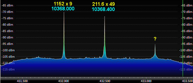
Above is the IF at 432MHz of my 10Ghz Rx sysrem. 10368MHz is downconverted to 432MHz. The strong signal at 432.000 (10368.000) is the 9th harmonic of the 1152MHz IF in my 1296->144 transverter. The signal near 432.400 (10368.400) is the 49th harmonic of the 211.6MHz signal generated by the Si5351a. I have no idea what the signal at 433.1MHz (10369.1) is coming from. It's not from the Si5351a. This is with the 10Ghz feed and Rx system in the shack, where there are lots of electronics generating all sorts of signals!
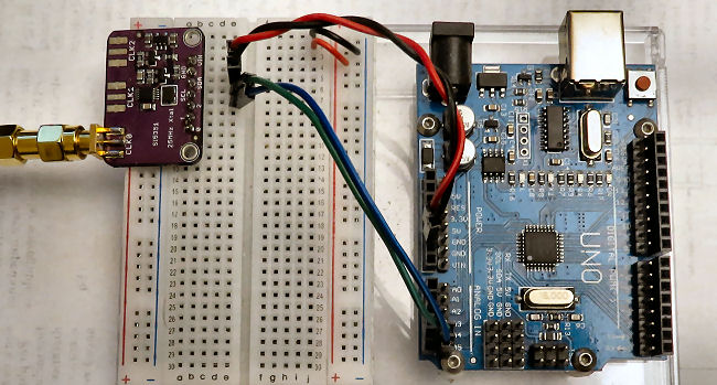
What do I need to build this?
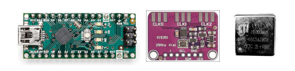
You need two things (maybe three if you want good frequency accuracy). First an Arduino MCU. A UNO or NANO model is fine. Second you need an Si 5351a clock generator breakout board. Total cost so far is maybe $10 (from China), maybe $20 if you buy from a US source on Ebay. There are 4 wires that connect these two components. A +5v wire from the Arduino to the SI5351a and a ground wire from the Arduino to the Si5351a. That takes care of the power. Then you need two IC2 communications wires. The SCL terminal on the SI5351a connects to an SDL terminal on the Arduino UNO/Nano (or the A5 pin) and the SDA terminal on the SI5351a connects to an SDA terminal on the Arduino UNO/Nano (or the A4 pin).
- Si5351a +V connects to Arduino +5v
- Si5351a GND connects to Arduino GNS
- Si5351a SCL connects to Arduino A5 or SCL
- Si5351a SDA connects to Arduino A4 or SDA
Some, more recent, Arduino UNOs have pins marked SCL and SDA, but they are just extra connection to the A5 and A4 pins.
That's it. The frequency generator is now finished. You can also add a stabilized reference source if you want high frequency accuracy and stability.
Next comes programming the Arduino so that it can get the SI5351a frequency. If you are unfamiliar with the Arduino and Arduino programing using the Arduino IDE, see ARDUINO. The program is simple. Here it is:
#include "si5351.h"
#include "Wire.h"

Si5351 si5351;

unsigned long long freq  = 21160000000ULL; // 211.600000MHz x 49 = 10368.4Mhz

void setup() {

  si5351.init(SI5351_CRYSTAL_LOAD_8PF, 0, 0);
  si5351.drive_strength(SI5351_CLK0, SI5351_DRIVE_8MA);
  si5351.set_freq(freq, SI5351_CLK0);

}

void loop() {
}
This will set the SI5331 to output 211.6MHz on output #0 (CLK0). The 49th harmonic of this signal will appear at 10368.400000MHz (subject to reference frequency errors). And you are done. Though the spec on the Si5351 used to be 160MHz and more recently seems to be 200MHz, most will work just fine up to at least 220MHz. Some samples will go all the way to to around 290MHz.
What am I missing here. Sounds too simple
Well, the reference clock for the Si5351a breakout board is a simple 25MHz crystal oscillator (an XO not a TCXO). It won't be at exactly 25.000000000MHz and it will drift with temperature. The drift rate at 10Ghz will be 49x the drift rate at 25MHz and the frequency error will be 49x the error at 25MHz. It will still produce a useful test signal, but not one you can use for stability checks or exact frequency calibration at 10Ghz. Taking a random Si5351a breakout board, I measured the crystal frequency as 25.000193 MHz at room temperature.
A synthesized 211.6 signal was actually at 211.60168MHz and the 49th harmonic was at around 10368.48MHz rather than the intended 1038.4000000 MHz. That's 80kHz off where it would have been with a 25.000000Mhz crystal. Not terrible if you just want some sort of audible signal. The signal is strong enough to easily find when tuning the band around 10368.4 MHz but obviously not much use for exact calibration. It would drift around slowly over a few kHz. If you have a good frequency counter for 211.6MHz, it's easy to predict where the harmonic will be.
There are two ways to deal with frequency accuracy and stability. (1) remove the 25MHz crystal and inject a few mW of a GPS locked (or calibrated OCXO) signal at 25MHz. This is easy, though you almost certainly won't have such a stabilized 25MHz reference signal at hand. (2) Remove the 25MHz crystam and inject a few mW of a 10MHz signal from a GPSDO or calibrated OCXO. A 10Mhz signal is probably a lot easier to find (and cheaper) than a 25MHz siagnl. You can get a good (used) OCXO for under $10 (China), maybe under $20 for a US source on ebay. I bought (5) 10MHz OCXO's for $25 last time I shopped for them (Ebay, China). Of course, if you change the Si5351a reference frequency you need to change the program a little , but that's relatively east as the reference frequency is one of the parameters in the si5351.init command. See si5351.h Arduino library for details
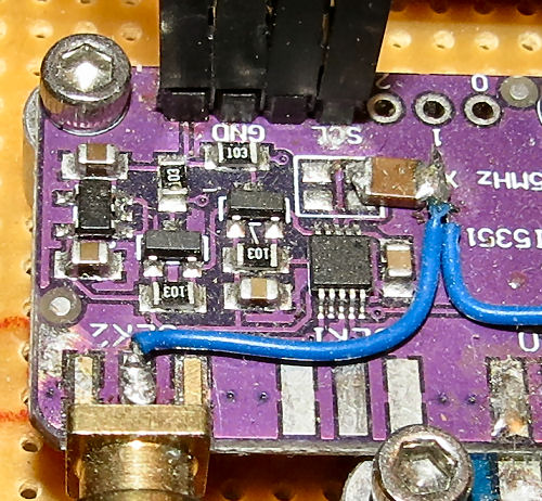
Above is an Si5351a board modified for a external reference signal. A few mW of reference is all that is needed. The spec sheet suggest a 1v pp signal for 25/27MHz. The crystal is removed and the external reference signal is connected to two of the crystal pads ia a 0.1uF capacitor is shown. The coupling capacitor value is not critical. In this configuration the CLK2 output was disconnected from the SI5351a and used as an input connector for the external reference
The output spectrum of the Si5351a may not be super clean and may show significant phase noise, However, you are just looking for a signal as a frequency marker and a RX tester, it's good enough. You should not have any problem recognizing the 10Ghz signal. You may not even see the harmonics of any spurs and they will be well away form the main signal even if they are detectable.
You can fancy things up with LCD displays, dials and buttons to set frequency etc., but for a single frequency generator, you don't need to. Just power it up and you will have your signal. It should be detectable with the Si5351a within maybe 6-10ft from the 10Ghz feed horn, even without any sort of antenna attached to it. If you run it into a coax to waveguide transition and add a small horn, it will be detectable at a greater distance. Even better, run the signal into a wavegude bases harnonic or comb generator using a high spped microwave switching diode. Of course all this is unnecessary if you just want a signal for testing an 10Ghz reveiver.
Good frequencies to multiply from
Here are some suitable Si5351a frequencies to multiply to the 10368.000 to 10369.000 region. These frequencies can be accurately expresses as rational fractions for use with the Si5351a's fracational-N synthesizer.
- 10368.000 = 128.000 x 81 nice round numbers (integers)
- 10368.150 = 159.510 x 65
- 10368.200 = 220.600 x 47 low multiplier and should be in the range of the si5351a
- 10368.250 = 154.750 x 67
- 10368.300 = 203.300 x 51 or 181.900 X 57 or 121.980 X 85
- 10368.400 = 211.600 x 49 low multiplier and should be in the range of the si5351a
- 10368.600 = 188.520 x 55 within spec of Si5351 (up to 200MHz)
- 10368.800 = 159.520 x 65
- 10368.900 = 252.900 x 41 Lowest multiplier but might be pushing the range of the Si5351 a little bit far
I use 211.600 x 49. My Si5351a boards seem happy there, and 10368.400 is just above where most of the activity is, so it could be left running as a martker and not interfere with any EME signals.
Checking Image Rejection
This source can also be setup on the image frequency of a 10Ghz receiver to check the image rejection characteristics of the receiver. 160.000 x 63 and 224.000 x 45 will both generate a signal at 10008.000 Mhz, which is the image frequency of 10368.000MHz in a system with a 144MHz IF.
Other Chip Options
The ADF4351 PLL module covers 35M-4.4GHz. It's usually configured for 10kHz steps, though 1kHz steps are possible. Things get tricky at smaller step sizes. In contrast the Si5351 can do 0.01Hz steps and is specified for operation from 2.5 kHz to 200 MHz (though most will work up to about 220MHz). There is an Arduino library for the ADF5351 and the clock frequency can be as low as 10MHz. There are Chinese ADF4351 boards with an included MCU and display. They typically use a 25MHz unstabilized XO as their frequency reference and they typically have a 10kHz minimum step size. Since they are programmed for a 25MHz reference, you can't use a 10MHz reference since that will make all the frequency calculations incorrect (and it may not work). You could use a 25MHz reference (which I guess you could derive from an Si5351 operating at 25MHz with a 10MHz GPSDO refence).