.jpg)
Stable 25MHz reference
Many frequency synthesizers use a 25MHz clock as their fundamental frequency reference. While ultra stable OCXO (Oven Controlled Crystal Oscillator) 10MHz oscillators are easily find and can be purchased for between $10 and $30 on eBay. You can find a few 25MHz OCXOs new for as little as $70 or as much as $650. I have also seen 25MHz OCXOs on ebay from time to time. However by using a low cost clock multiplier chip it is possible to generate an ultra stable 25MHz signal from a low cost 10MHz OCXO source, and by going this route you can also use a voltage tuned double oven OCXO for higher stability and the ability to tune it to exactly 10.000000000 MHz.
The stability of an OCXO or, even better, a DOCXO (Double Oven Controlled Crystal Oscillator) depends on the manufacturer and the individual model. Typically they are at least 100x more stable than a TCXO (temperature Compensated Crystal Oscillator. More than stable enough for a frequency reference at 10Ghz. They are probably not quite as stable as a good GPS locked 10Ghz reference (especially over weeks and months of operation). 1Hz stability at 10Ghz requires 1 part in 1010 stability. The better DOXOs have a stability of maybe 1 part in 1010 or even 1 pert in 1011 over a fairly wide temperature range. Of course you get what you pay for and a $10 used OCXO from China via eBay almost certainly won't be quite that good. However most will hold within a few Hz at 10Ghz, and that's just fine for 10Ghz EME work.
Voltage tuned OCXO and DOCXO oscillators can be tuned over a very small range so they can be set to exactly 10.000000000.... MHz. They are more useful that fixed units which will be very close to 10 MHz but which can't be tuned if they are not exactly on 10.00000... MHz. The ideal would be a voltage tuned 10 MHz DOCXO. They do exist and I've bought them (used) from eBay for around $30.
The low jitter clock multiplier chip I have used is the NB3N502 from ON seniconductor. This chip is very easy to use. In this application you feed at a 10MHz signal, configure the state of a few control pins, and it generates a 25MHz output. By reconfiguring the control pins it can also multiply by 2x, 3x, 3.33x, 4x or 5x. H ave not attempted to measure phase-noise/jitter. The NB54502 sec shoot shows typical jitter of 15 ps One Sigma (rms)
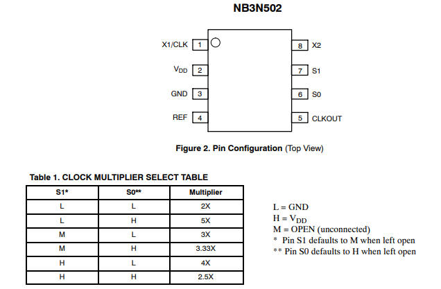
Connections for a 10Mhz to 25MHz clock multiplier are simple:
- 10MHz input
- +5v supply
- Ground
- Buffered 10MHz output
- 25MHz output
- High (5v)
- High (5v)
- N/C
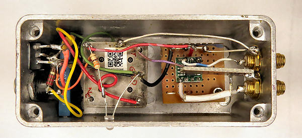
You don't need a PCB, point to point wiring seems to be just fine.
Applications might include use as a 25MHz reference for a 10Ghz LNBF or a 25MHz reference for a low cost Si5351 based frequency synthesizer. The output will be a square wave, so depending on the application you may need a 25MHz low pass filter to remove the higher harmonics.