.jpg)
EME dish feed optimization - what f/d?
We often see statements that a given feed design is optimized for a dish with a certain f/d ratio. Deep dishes with an f/d of 0.3 require a different feed than shallow dished with an f/d of 0.6. But what does this mean? What is "optimized"?
The performance of a parabolic dish antenna depends on how the surface is illuminated by the feed. If the feed concentrates all the RF power in the center of the dish, then the outer edges of the dish are "wasted" . On the other hand if the feed spread the RF power over too wide and area, then some of it doesn't hit the dish at all (this is called "spillover", so again that power is "wasted". So over what angle should the feed distribute power to the dish?
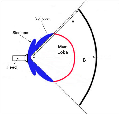
Interaction of feed with dish showing spillover and differences in free space loss (A > B)
Without going through all the math, I'll just tell you that for maximum gain, which gives maximum ERP (effective radiated power), i.e. the strongest transmit signal, the power density at the edge of the dish should be around 10dB less than the power at the center of the dish. There's a little bit of a catch here though. The feed is always slightly further from the edge of the dish (distance "A" in the figures above and below) than the center of the dish (distance "B" in the figure above and below). If the dish was spherical A would be equal to B, but for a parabola A is always greater than B. This is shown better in the more realistic illustration of a parabolic dish below. Since power density drops off with the square of the distance from the source, there's a "free space" loss factor involved in dish illumination. For a dish with an f/d ratio of 0.35 there's about 3.6dB more free space loss from the feed to the edge of the dish than from the feed to the center of the dish. For a dish with an f/d of 0.45 this value drops to around 2dB.
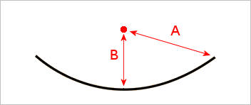
Free space loss in parabolic dish illumination
So to get an edge illumination that's 10dB down at the rim of the dish compared to the center with an dish of f/d = 0.45, the pattern from the feed in the direction of the rim should be 8dB down from that in the center of the pattern. For an dish with an f/d of 0.35 a wider feed pattern is needed, but the intensity in the direction of the rim of the dish now should be only 6.5dB down from that at the center.
But do we want everything optimized for maximum ERP (which equates to maximum gain and maximum transmit power)? Most EME stations want to receive as well as possible in addition to transmitting, and it turns out there edge illumination that gives you the best receiver sensitivity (best G/T ratio) is different from that which provides the most gain. This is because of "spillover" (see above figure). Spillover on transmit radiates power past the dish. On receive spillover means that the feed not only "sees" the signalreflected off the dish, but also the ground beyond the dish. The ground is warm and generated thermal RF noise which interferes with any received signal. The less spillover you have, the less additional noise you pick up and the weaker the signal you can hear. So from that viewpoint you'd want the feed to be concentrated on the center of the dish - but that would reduce gain and received signal strength. It turns out the best compromise between minimizing spillover noise and maximizing signal gain (highest G/T ratio) and it's probably an edge illumination value of around -15dB less than the center. If you were building a radio telescope which just listened, you might design the dish feed for this value assuming it's waveguide type feed.
But we aren't usually building an EME system just to listen, so there's a compromise between best Tx performance and best Rx performance, and that comes from a dish illumination that's probably somewhere around -13dB at the rim compared with in the center. This will give the strongest echoes.
In the table below the optimum dish f/d ratio is given for best Tx performance, best Rx performance and best Echo performance for three common feeds. The W2IMU dual mode horn is used for shallow dishes (often home constructed), while the OK1DFC Septum feed is used with many commercial dishes, such as those originally intended for satellite TV reception. The first number, maximum Tx gain, is usually given as the f/d for which the feed is designed. These numbers were generated using EMECalc.
| Peak Tx | Peak Rx | Peak Echo | |
| W2IMU dual-mode | 0.58 | 0.43 | 0.46 |
| OK1DFC Septum | 0.36 | 0.24 | 0.28 |
| OK1DFC Septum and Choke | 0.37 | 0.30 | 0.32 |
The first thing of note is that the best f/d for Tx and Rx are different, and the best f/d for echos is closer to the Rx number than the Tx number.
An obvious question to ask is how much difference does it make if you are optimized for Tx, Rx or Echo. Again EMECalc can help answer that question. It does depend somewhat on your system NF, so let's assume you have a fairly good 1296 EME system and an Rx noise figure of 0.25dB. Let's then assume you are looking at working a weak station with a signal strength expected to be around -24dB. With a given set of parameters for the Dx station, if you were using an OK1DFC feed with Choke on a dish with an f/d ratio of 0.37 (optimized for Tx), EMECalc predicts you would see the Dx station at -23.98dB. If the dish was f/d 0.30 (optimized for Rx), the Dx signal would be -23.24, a 0.74dB improvement. That may not sound like a lot, but with the f/d = 0.37 dish, you'd have to lower your Rx noise figure from 0.26dB to 0.11dB to get the same improvement! 0.74dB can easily be the difference between a weak signal decoding and not decoding.
It can also be useful to extend a dish, even if the extension isn't a very good parabolic extrapolation of the existing dish surface. This cuts down on fillover and so may lead to slightly improved Rx performance. If you got the shape of the extension exactly wrong it's possible it could mess up the beam, but I think this is probably unlikely.
Note: The modeling probably isn't good enough (or the input data isn't detailed enough) to predict signal strengths to 0.01dB or to accurately predict the difference between a f/d of 0.32 and 0.325 but the general conclusions and trends are valid.
So the point of all this is that the figure usually quoted for feeds (e.g. this feed works best with dishes having an f/d ratio of 0.37) depends a lot on how "works best" or "is optimized for" or "is designed for" means. The number you see may not be the number you want. You are generally going to get overall better performance with a dish slightly deeper (lower f/d) than one which would deliver maximum gain (=optimized for Tx). Alternatively you can say that the tuning of a feed (e.g. waveguide diameter and Choke size and placement) for maximum gain might not always give the best on-air (Rx/Tx) performance.
My choice is to tune for maximum receiver sensitivity (G/T ratio). That puts you slightly closer to the tuning for best echoes than tuning for maximum gain. It's also much easier to do, since if you tune for maximum sun noise, you're tuned for best Rx performance (best G/T). It's hard to measure absolute gain or precise echo strength. You can easily measure sun noise to within 0.1dB with most EME capable systems.
Reading
How the Professionals do it - A presentation on Radio Astronomy antennas and receivers from the NRAO