.jpg)
Q65- Step size and Drift compensation
Caveat: Any explanation of the Q65 algorithm here is my own simplified understanding of what is going on. The actual intricate details of the decoding process are probably understood by only a few people, and I'm not one of them. What is presented here may give you an overall idea of what is happening, but is not intended to be a 100% accurate detailed insight into the internal processes going on inside the Q65 decoder.
To start with, let's take a look at a Q65 signal. In this case it's a signal that might be found on 1296EME. The Doppler spreading is 25Hz.
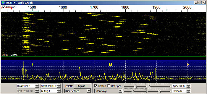
On the left, at 1480Hz in this case, is a row of synchronization tones. Each tone is centered at 1480Hz and is 25 Hz wide. The sync tones occur in a fixed, known pattern. The Q65 "package" consists of 85 channel symbols. Here's a typical channel symbol package. The "0" entries are the sync tone transmissions in in every message they will appear in exactly the same place. The other symbols will dependend on the content of the message:
0 38 29 31 2 41 53 19 0 55 26 0 0 10 0 5 41 3 38 32 31 0 0 55 10 0 0 19 28 7 58 36 0 27 0 45 11 0 17 62 44 60 22 56 52 0 3 55 1 0 30 32 33 44 0 56 44 4 30 0 57 0 45 3 17 0 41 46 0 37 47 7 61 0 26 0 61 44 42 33 58 2 35 31 0
You can see the sync tone transmissions (19 of them) are distributed throughout the message and are the first and last tones. From the distribution pattern of the sync tones, Q65 can figure out what part of the message it is looking at, even if it misses the start of the message. The message bit are identified by their frequency with respect to the sync tone frequency and where they occur in the message can be identified by their position relative to the sync tone pattern. With a signal like this where every measurement of the sync tone shows it at the same frequency, decoding the pretty simple because every tone can be identified pretty easily in terms of frequency and position in the message.
The message contains a good deal of redundancy and forward error correction, so sizable chunks of the message can be missing and Q65 can still identify the tones and their position and from that can produce a decode of the original message. Q65 is pretty smart.
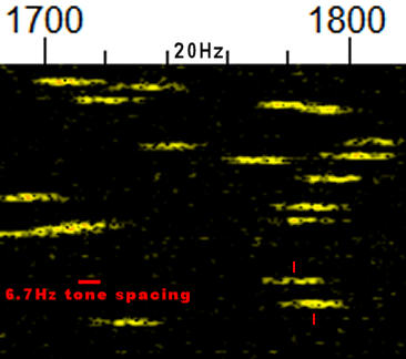
In Q65-60C the message tone spacing is about 6.7Hz as shown in the figure above. The center frequencies of the two tones on the lower right are separated by about 6.7Hz and so represent the frequencies for message tone "X" and message tone "X+1" (e.g, 45 and 46). So to know what a given tome represents, it's center frequency with respect to the sync tone must be know with an accuracy of around +/- 12Hz. If you get the frequency wrong by more than maybe 6Hz, you might read a 34 as 35 or a 34. Knowing where an individual tone is centered is critical to accurate message decoding.
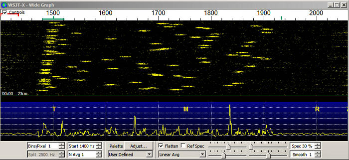
So all is good when the signal isn't drifting and Doppler tracking is being made in small steps (e.g. 1Hz). However signals aren't always that stable. Drift can occur for a number of reasons. Quite a few rigs will drift on Tx if not locked to a stable reference due to internal heating and an imperfect TCXO reference. All rigs tune in discrete steps, sometimes 1Hz, sometimes 10Hz, sometimes 20Hz. Between those steps the signal will drift. If you are listening to a QSO between two other stations you may see drift due to changes in Doppler shift not being the same for you as for the other stations. It all depends on the echo mode in use (CFOM, on-echo etc). So what happens if the signal is drifting, or if Doppler tracking is in 10Hz or 20Hz steps? Things get complicated. Below is a signal that's drifting at about 24Hz/minute.
So how much drift is too much drift? If we are looking at drift due to the Change in Doppler with time, from experience on the air and and from simulation testing,you can get excellent decoding of typical 1296 Q65-60C EME signals and Q65-60E 10Ghz EME signals without any Doppler tracking at all. There's typically no appreciable sensitivity loss. If the DX station is using a rig which is also drifting in the same direction that the Doppler is changing, then you might have a problem. but you might have a problems even if you were Doppler tracking in 1Hz steps too, depending on how bad the drift was.
The same is pretty much true if you are Doppler tracking in 10Hz or 20Hz steps at 10Ghz with Q65-60E. Frequency steps of this size don't affect decoding sensitivity. However on 1296 using Q65-60C, there's a bit more of an issue (see above figure). If there is a 10Hz or worse, a 20Hz step right in the middle of an Rx period, decoding can be compromised slightly. Worst case with a 10Hz step for 1296 using Q65-60C is a sensitivity reduction of maybe 1dB. With a 20Hz step this can go as high as a 3dB loss of decode sensitivity. This is still pretty good. Q65-60C will decode a typical 1296 EME signal down to maybe -26dB for a single period decode. So that might mean -25dB with a 10Hz step in the middle of the period or -23 with a 20Hz step.
What about drift compensation?
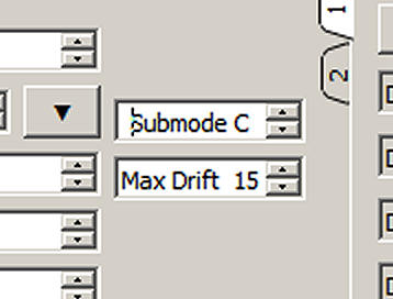
What indeed. Q65 has a "knob" that can be turned form 1 to 50 and which is marked as being "max drift" as shown above. I believe this was added as a sort of "quick fix" for those doing 10Ghz aircraft scatter, where Doppler frequency and rate of change can't be predicted and where it is changing fast. I don't think it was ever really intended to be a fix for poorly performing radios. It was also intended for Doppler changes that were smooth in time (linear drift?), not sudden step changes or rigs that were unstable and drifting in different directions at different rates at different times.
On badly drifting signals, using some degree of drift compensation can decode signals that would not otherwise decode. I've used it on the air a few times for this purpose on 1296. It's usually a new station which doesn't yet have frequency under proper control. It's typically not a critical setting if 15 works, so will 25 and 50. There is a small loss of sensitivity as drift compensation is increased, but its not much (<1dB?) and when you need it, you need it.
Though it was never intended to compensate for step frequency changes, some simulation tests have shown that it can sometimes help (and I don't know why). Under some extreme conditions using a high setting can result in a false decode. A Grid can be reported as a signal report ("e.g. R+23) when AP is being used (as it almost always will be) and the Decode marker can be Q0, Q1, Q2 or Q3 when you would expect Q3. It was never intended to be used like this, so don't complain if it does strange things.
There is an explanation of the drift rate compensation in Quick-Start Guide to WSJT-X 2.5.0 and MAP65 3.0 Here it is:
Drift Compensation: A Q65 user control Max Drift appears on the main windows of both WSJT-X and MAP65. The Q65 decoder measures and compensates for signal drift up to (symbol rate) x (Max Drift) per transmission. The Q65-60x submodes have symbol rate 1.667 Hz, so setting Max Drift to 15 accommodates drifts up to 25 Hz per transmission. Similarly, Q65-15x submodes have symbol rate 6.667 Hz, so Max Drift = 40 accommodates drifts up to 267 Hz per transmission (as might be required for 10 GHz aircraft scatter). It’s best to keep Max Drift set to 0 unless drift compensation is actually required, and otherwise set it no higher than necessary. Drift compensation is active in MAP65 only for signals within +/- FTol of the selected QSO frequency.
If I'm understanding this correctly, this suggests that the maximum drift rate than can be compensated for when using any of the Q65-60 modes from 60A to 60E is 1.667 x 50 = 83.33 Hz per transmission. A Q65-60 transmission is 51s long, so that would correspond to a maximum drift rate of 98Hz/minute. So the number in the box for 60s transmissions would be about 1/2 the drift rate in Hz/min. A number of "10" in the box would then seem to correspond to compensation for up to a 20Hz/min drift, a "25" would compensate for up to about a 50Hz/min drift and a number of "50" could compensate for up to 100Hz/minute drift.
Shorter periods should need less use of drift compensation because the signal frequency will change less over the shorter period then over a longer period. So a 60C signal that won't decode without drift compensation, might well decode without any drift compensation if the mode was changed to 30B.
Bottom Line
Unless you are failing to decode a signal that looks like it should be decoding, leave drift compensation set to "0". That is of course exact what Joe says in the user guide "...It's best to keep Max Drift set to 0 unless drift compensation is actually required...". If a signal is obviously drifting and it's not decoding, then dial in some drift compensation. Maybe start at 25 and go up or down if necessary. Too much drift compensation can reduce sensitivity slightly and possibly induce some false decodes under extreme conditions. On the right signal, using drift compensation can get you a decode when without it you won't, but this is pretty rare. I'm quite active and I've only seen it a few times. There aren't many stations with badly drifting signals on 1296 and in most cases when that happens, the station operator fixes the problem quite quickly. If a signal with a good trace will not decode there could be several reasons for this. The Tx station could have changed their message in the middle of the transmission for example. There are audio latency and dropout issues which manifest themselves in failure to decode. Restarting WSJTX will usually cure audio issues.
When it comes to tracking step size, 1Hz steps are preferred on all bands. 10Hz steps appear to be no problem on the bands from 1296 and up and at 10Ghz, 20Hz steps seem to be just fine with typical Doppler change rates and spreading levels. 20Hz steps on 1296 would be expected to lead to occasional decode problems with some loss of sensitivity under certain conditions, but 20Hz steps would still work OK most of the time. 20Hz steps on the lower bands, such as 144MHz would likely lead to a lot of problems, but on those bands, not using doppler tracking at all works quite well since Doppler changes slowly. You can just use RIT to set the initial Doppler shift.