.jpg)
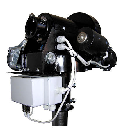
The SPID BIG RAS HR Az/El rotator
NOTE: SPID provide few, if any, detailed specification on their rotators (other than external dimensions and operating parametesr). So much of what is on these pages is a combination of a little information which can be gleaned from the limited info SPID provides and a lot of observation and reverse engineering. Don't take anything written here as the "100% true and correct". That would have to come from SPID, should they decide to make the details of their rotator systems public. You may find some information via these official or semi-official links:
On this page I only describe working on the elevation axis of a SPID BIG RAS/HR, but most of the warnings and suggestions apply equally to the Azimuth axis system. I have also worked on the smaller SPID RAS/HR, which has basically the same design, but is a little smaller.
First let me say that it's about 100x easier to work in the SPID rotators on the bench that it is with them on a tower with an antenna attached. Sometimes you have to work on them when installed, and in general, except for major repairs, it can be done. However these rotators are not designed for "in service" repairs. The only really practical repair you can do on the rotator is to replace the motor and integrated gear-box if it fails.
One of the major issues is that to remove the motors you have to get a three mounting screws. One is usually easy to get at and often a hex head bold. At least one (and sometimes two) of the others are typically slot head screws and you have to work at an angle to the axis of the screw. This is not the way slot head screws are designed to work! If they are not over-tightened it's not too bad. If they are, you may have problems.
But that's not the worst of it! To get at the hidden, off angle, slot head screws you have to remove the cover over the main gear. The azimuth drive cover is held in place by 5 or 6 sheet metal screws which go into holed (not tapped holes!) in the rotator housing. The Elevation drive cover only has two screws holding it in place as shown below.
These screws on both the Az and EL drive covers aren't hard to get at, but once you've removed all the screws, you can't move the covers far because they around the axis and the bolts holding the axis shaft in place prevent the covers from being moved far. Not an issue on the bench because you can remove the bolts and slip the covers right off, but you can't do that with the rotator in place on a tower and an antenna attached. So with the rotator on a mast and an antenna installed, you are working through a 1/2" gap to get at a slot head screw you can't really see, with a long flathead screwdriver - and at an angle to the screw! It's not fun, but is possible(I've done it on a SPID RAS/HR).
I'm not sure why they didn't use a hex socket head bolt since you can work on them off angle with a ball head hex wrench. But they didn't.
The azimuth motor on the SPID BIG RAS has slightly easier access. Two of the pots are external hex head bolts and so are easy to remove. The third one is a flat head screw whic is under the cover-plate of the main azimuth rotation gears. Again you can't take the plate fully off with the antenna on the mast because the bolts that hold the rotator to the mast get in the way. You can open up a gap that's just wide enough to get a log screwdriver in the slot in the head of the screw (though you'll still be at an angle to the axis of the screw).
Once you have loosened the screws holding the motor in place it just pull out. SPID use fairly long screws to hold the motor in place, so you have to loosen them, Pull the motor out a bit and then loosen them a bit more and so on until the motor is free. The screws can't be backed out all the way because (at least) one of them hits the main ring gear when backed off by a small distance.
The difficulty of removing the main gear covers also makes it quite hard to apply grease to the main output gearing worm and rotator. If you do want to clean up and add grease you need grease specifically designed for high pressure use. Worm and ring gears have sliding high pressure contact. The gears slide against each other, then don't just push on each other, so lubrication is critical. Typically any "extreme pressure grease" intended for automotive use will probably be OK. They may typically have molybdenum disulfide, lithium or graphite additives which can help them stick to the metal surfaces and improve lubrication.
Finally here's a shot of what you run into trying to remove the elevation motor of a SPID RAS/HR (not BIG RAS) mounted on a mast with antenna attached.
I counted 120 teeth on the main final ring gear, and measured the rotation of one tooth (3 degrees) for every rotation of the shaft coming out of the motor gear-box assembly. If the final reduction ratio is therefor 360:3 or 120:1, then to get an overall reduction ratio of 6120:1, the reduction ratio of the gear-box attached to the motor must be 51:1. So the sequence appears to be:
Motor rotates 51 times (18320 degrees) --> Gear-box --> output shaft rotates 360 degrees --> gear-box --> axis rotates 3 degrees
The incremental encoder reads rotation of the shaft coming out of the motor/gear-box unit (not the final Az or El axis)
Though I have not looked directly at the gearing of the smaller SPID RAS rotator, it's quoted by SPID as having an overall gearing of 4950:1. Based on some other factors and comments, I believe this may correspond to a gearing on the motor output of 55:1 (i.e. 55 rotations of the motor to give one rotation of the output shaft). This them corresponds to a 90:1 gearing in the final drive. This leads to one rotation of the motor/gear-box output resulting is 4 degrees of axis rotation (in contrast to the 3 degrees for the BIG RAS).
The "HR" (High Resolution) encoders are magnetically coupled Hall effect quadrature generating sensors. I believe the non-HR versions use magnetically operated reed relay with one pulse every 0.5 degrees for the BIG RAS and one pulse per degree the the smaller SPID RAS.
The SPID RAS HR uses an incremental encoder that generates 32 full (x1) quadrature transitions for every rotation of the motor/gear-box output shaft (4 degrees of axis rotation). This results in 8 transitions per degree in x1 quadrature mode, or a transition every 1/8th degree (0.125 degrees).
According to SPID specs, the SPID BIG RAS HR, uses the same(?) encoder, with 32 x1 quadrature transitions for every rotation of the motor/gear-box output shaft. In the case of the BIG RAS this is a 3 degree axis rotation. This would result in a 1x quadrature transition every 3/32nds of a degree (0.09375 degrees).
The SPID controller presumably counts these transitions and moves the axes to the nearest 0.2 degrees for the SPID RAS and the nearest 0.1 degrees for the BIG RAS. It's an odd system but it works. They could have read the quadrature signals in 4x mode and had 4x the resolution. I've done that myself with a parallel hardware decoder - an it works, but I guess reading them at 1x and reading out to 0.2 degrees (RAS) and 0.1 degrees (BIG RAS) was "good enough" for the intended use of these rotators and possibly represents their limit of mechanical precision.
One end of the worm gear couples to the motor shaft. The other end is held in place by a large screw with a large locknut marked "DO NOT REGULATE". This means "Do Not Adjust" and it's used to set worm gear clearance and bearing pressure by the SPID factory. Under normal circumstances you should not need to make any adjustments.
Both ends of the worm gear are supported by open race bearings. That means there are loose ball baring in an open race and that if you back out the large screw, the ball bearings will fall out of their position. They are not held in place by any sort of housing. Putting the balls back in place is not easy and is probably close to impossible with the rotator mounted on a mast and an antenna in place. So be careful if you decide to make any adjustment!
The adjustments you can make (though probably shouldn't unless you know what you are doing) are pre-loading the bearings and adjusting the backlash. The tighter the screw is, the more pressure is placed on the ball bearings. With too little pressure the balls are not secure and not in full contact with the races. This means they can wobble around, so it is an undesirable condition. On the other hand, if you apply too much pressure, the balls are held tightly in the races and there is increased friction. This will lead to "sticky" rotation and excessive wear. You want "just the right amount of pressure" to hold them securely in place without them being held so tightly that they bind and wear. It's hard to define this point and setting them can be a matter of experience and "feel". Basically, it's finger tight plus a little bit more! Normally this is factory set and you shouldn't touch it. At least that's what SPID would say, and they are probably right.
The second adjustment comes from the fact that the large screw is in a vertically elongate slot, not a round hole with zero clearance. It can move up and down. This moves the worm gear closer to or farther away from the main ring gear. If the spacing is to far there will be a lot of backlash (free play) in the gearing system. If it is too close (i.e. pressed tightly against the main gear), there will be little or no backlash, but there will be a lot of pressure on the gear surfaces leading to more rapid wear and higher friction. Again you are looking for "just the right amount" of clearance. This would be just a tiny bit of free play. Again it's a matter of feel. It's factory set by SPID and shouldn't need adjustment unless the gears have worn significantly and opened up the gap.
So once again, the official word from SPID is "DO NOT REGULATE". If you do decide to mess with the settings, the important caution is do not back out the screw more than a fraction of a turn. If you back it all too much, the ball bearings will fall out of place and you will wish you had left it alone! The only reason to back it out would be if you had to chance the worm gear or there was some issue with the bearing and you needed to replace the ball bearings (a very unlikely condition).
One way it which it might be possible to tell if you have an adjustment that is too tight is by monitoring the current drawn by the motor when it is under no load. With the motor removed from the rotator and 12v applied, I saw a constant current draw of about 300mA. When mounted on the rotator the current draw was quite similar (maybe 350mA), with a slight variation which was synchronized with the worm gear rotation rate. If the load on the ball bearing was too high, the current increased to around 600mA with fluctuation between about 500mA and 700mA as the worm gear rotated. I could see a similar increase in current when the worm was pushed too hard against the ring gear. So if you see high, fluctuation current draw, you certainly don't have the settings correct. I'm not 100% sure that if you don't see a higher and con-constant current it means that all is OK, but it's at least something to look for. None of this is SPID advice, just my personal observation on the one sample of the BIG RAS that I have looked at.
So I am not recommending you make an adjustment. If you decide to do so, it's 100% your responsibility. While I believe what I've written here is (mostly) correct, none of this is "SPID approved". Maybe things are different of different rotator models. Maybe there were design changes made during production of any particular rotator model. Maybe I'm just wrong. I take no responsibility for any unforeseen problems you might run into with your rotator. You have been warned.
Just some random notes on pinouts etc. here as I make repairs!
The plug on the end of the cable coming from the encoder. Due to a cable snag, a number of connections in the AZ plus were pulled out of their pins in the plug. Here are the color codes that I found for this cable/plug connection by looking at the EL plug and assuming the color coding was the same (and it was!)
In some circles, SPID rotators don't have the best reputation. Some people reports of problems with them maintaining AZ/EL calibration. Other's report no issues. It's not always clear which rotator and which controller they are using though. The loss of calibration can be real as I have seen with my SPID RAS/HR and MD-02. Typically it tracks very well when just following the moon, but I have observed at times that if you are moving the antenna around in small steps for a while, such as when trying to peak on a signal, it can miscount pulses and go out of calibration. I'm pretty sure this is a controller issue, not a rotator or sensor issue but I can't be 100% certain of that. Note that SPID have now (10/2021) made available some revised firmware in Beta test according to the www.rfhamdesign.com website. I have not yet tested this. SPID also comes in for criticism in terms of support in the USA (basically there isn't any), and for not publishing detailed engineering drawings of the rotators and schematic of their HR controllers. This potentially makes troubleshooting difficult.
The rotators themselves (at least the RAS/HR and BIG RAS/HR) are built more like Soviet era tanks than swiss watches. No CNC machining the housing out of a block of steel, it's make up of steel sections welded together. In places, instead of tapped holes and bolts they use clear holed and self tapping screws. Not really a problem, just an observation. Getting at some of the bolts that hold the motors in place can be difficult (or very difficult), especially with the rotator mounted on a mast and with an antenna attached. They can usually be replaced "in-situ" if they fail, but it's far from a fun or easy process! Even on the bench it can be a bit of a challenge!
Despite these issues, SPID rotator systems can actually work pretty well and their price (if purchased from the right dealer) is generally very competitive. I've been running a SPID RAS/HR with a SPID MD-02 controller of at least 4 years, with no significant problems that were not my fault! I also now (since 10/21)have a BIG RAS/HR and MD-01 controller system working and so far no problems. I do keep a careful eye on calibration (see EMA Antenna Alignment).
I would like to thank Frank Potts, NC1I, for making the SPID BIG RAS/HR available to me, and Frank Postmus from RFHamDesign for assistance when I've run into problems.
Taking the rotator apart for servicing or repair
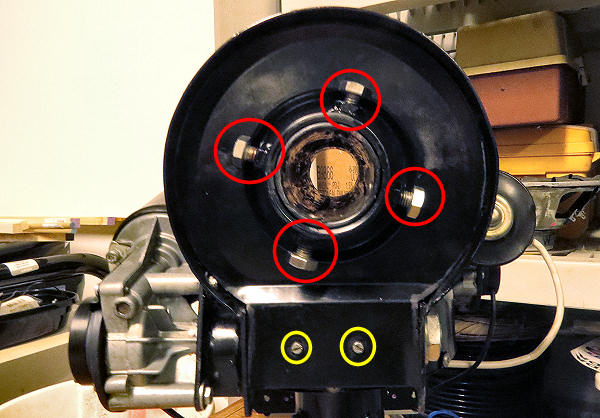
The two screws (yellow) hold the El drive cover plate. With a little encouragement it will pop off when they have been removed. However to remove it completelt required removing any El axis, the four axis locking bolts (red) and the retaining ring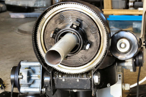
The Elevation axis gearing after the cover has been removed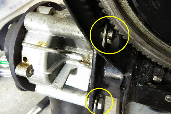
Two of the bolts that hold the motor in place. The easy one is the hex head bolt (center, lower). The harder one (center top) is a slot head with no easy access.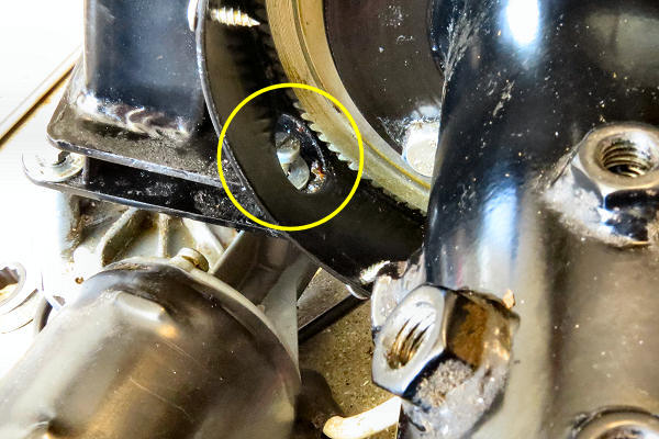
The 3rd screw is accessible only when the cover for the azimuth drive has been removed. Again a slot head screw with no direct access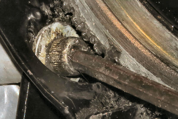
Replacement hex socket head cap bolt with off-axis ball-end hex wrench. With a 5mm socket and a 3/16" (4.75mm) ball end wrench you can get further off axis and still have good torque on the bolt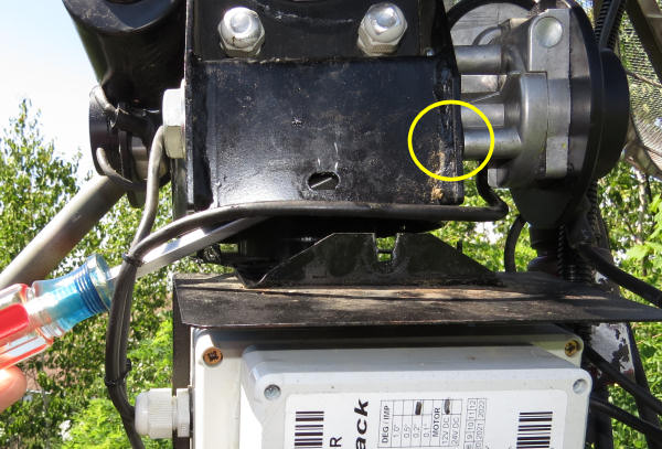
Inside the Az compartment is the hidden flat head screw holding the El motor on. The screwdriver would be horizontal to properly loosen this screw, but you can see the angle it has to be used at.Gearing
The SPID BIG RAS HR is a double worm gear system. The motor rotates a worm gear which in turn rotates a ring which is attached to the output shaft of the motor/gearbox assembly. The output from this motor/gear-box then drives the worm gear of the final (heavy duty) stage. On their website SPID give an overall gearing for the BIG RAS as 6120:1. Presumably this is the ratio of the actual rotations of the 24v motor shaft to final rotation of the Az or El axis.
HR Encoders
Adjustment
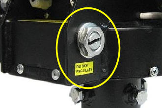
"DO NOT REGULATE"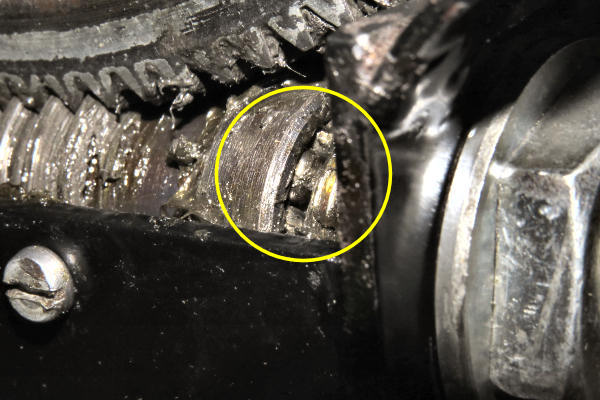
The uncaged ball bearings are visible in this view. Back the screw out and they fall out the the race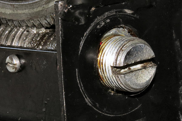
When the large locknut is removed it reveals that the screw is in an elongate slotPineouts and miscellaneous notes
Comments on SPID rotators in general
Acknowledgments