.jpg)
Antenna Aiming Calibration
Peaking on Echoes, Sun and Moon noise when you have a narrow beamwidth and/or a weak or noisy signal
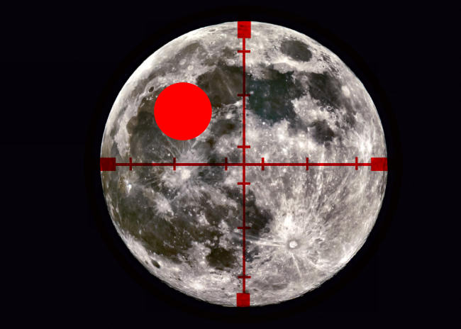
The red circle is about 0.1 degrees in diameter, the 1dB beamwidth of a 2.4m dish at 47GHz
Once you have built an antenna tracking system that works, the next question is to figure out exactly where your antenna is aimed. On the lower bands, this isn't a big issue singe antenna gain tends to be quite low and beamwidth quite large. For example an array of 8 x 14 element Yagis on 144MHx might have a gain in the region of 22dBd and a 3dB beamwidth of around 12 degrees. The 1dB beamwidth is around 7 degrees. That's a 1dB beamwidth that's 14x the diameter of the moon. So for the purposes of EME, just looking sighting along the boom you make sure it's pointing in the general direction of the moon is good enough to ensure you aren't losing any signal due to aiming errors.
At the other end of the spectrum, take a look at a 2.4m dish used at 47GHz. Now the gain is around 60dBi. The 3dB beamwidth is 0.18 degrees and the 1dB beamwidth is around 0.1 degrees. You can't tell where it's pointing by eye when the target is a 0.5 degree diameter moon.
There are two ways to make sure your antenna is actually pointing where you think it is. Assuming you have good azimuth and elevation sensore, with high enough resolution for your needs, you can peak the antenna on Sun noise, or, in the case where you antenna is large enough and the background is quiet enough (which generally means one f the higher frequency bands), you can peak the antenna on moon noise.
When the antenna beamwidth is significantly larger then the 0.5 degree beamwidth of the moon (or sun), you can gust move the antenna around for the maximum noise reading and you can be pretty sure that you are pointed at the center for the moon (or sun). However, when your beanwidth is smaller then the diameter of the source (sun or moon), this isn't a very accurate method of pointing. In that case you can get a "flat top" as you scan the bean across the target. Noise comes up to a maximum as the bean scans across the targer, then stays pretty much constant for a while, then falls off again. There's a better way to center the antenna on the target.
The (Gaussian) shape of the curve is the same for all beamwidths, so the same plot can be used for any beamwidth by appropriately scaling the X axis. To find the gain loss for an antenna with a 3dB beamwidth of 2 degrees when the pointing error was 0.5 degrees, you'd look at the loss corresponding to a value of 0.5 * (5/2) = 1.25 on the x-axis, which is around 0.7dB. One characteristics of a Gaussian are that the rate of change of slope (change of gain) with offset angle is zero at the peak and increases as you move away from the peak.
So the aiming calibration steps are as follows.
- Peak the antenna on the target (sun/moon). Note the power reading. Call it P
- Move the antenna slightly up. Enough for a significant drop in signal level. This may be a 1 degree step for a larger beamwidth or a 0.1 degree step for a smaller beamwidth.
- Note the new power reading. Let's call it U1
- Move the antenna back to the starting point.
- Now move the antennas down by the same amount you moved it up. Call this D1
If the antenna was properly centered on the target in step 1 above, P-U1 will be equal to P-D1, i.e. the power will prop off equally on either side of the starting position. If the signal does not drop off equally, you were not centered on the target in step 1. If the signal drops off more when you move up than when you move down, you need to move your starting point down a bit and vice versa. Repeat the process until the signal decrease when moving up is the same as the signal decrease when moving down. At that point you are centered in elevation.
Then repeat those steps, but this time moving the antenna left and right instead of up and down. When you get the same drop in signal strength when moving left and right, you are centered in Azimuth.
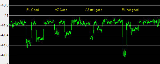
This is a plot of a moon noise test with a 0.85m dish at 10GHz. The first two dips show what happens when the antenna is offset by +/- 1 degree in elevation and azimuth than it's centered on the moon. The noise drops by equal amounts on either side of the properly centered antenna. The second two dips show what happens when the antenna isn't correctly centered. The sun noise maximum appears to be the same in both cases because the peak measurement is not very sensitive to offset. For 1296 this doesn't really matter, but for precision work on the higher bands, like 47Ghz, it does. When the beamwidth is smaller then the moon, both stations involved in a QSO should be pointing at the exact center for the lunar disk. If one is point a bit to the left and the other is pointing a bit to the right, both may be peaked on moon noise, but they won't be peaked on each other!
This process is relatively easy using software like PstRotator, which allows you to offset the antenna position in 0.1 degree steps while tracking. A 0.1 degree pointing accuracy is more than good enough for 1296, usually good enough for 10Ghz operation, but many not be good enough for relatively large dishes on 47Ghz. Custom tracking software may be needed for those bands, though the 1dB beamwidth of a 2.4m dish at 47Ghz is 0.1 degrees, so 0.1 degree steps may be just OK.
Peaking using Sun Noise, Moon Noise or Echoes
This technique of looking for an equal drop in signal when the dish is moved up/down and left/right can be used for any method of peaking an antenna. It could be peaking on Sun noise, peaking on Moon noise or peaking on Echoes. When signals are strong and stable you can just peak using the signal strength at the peak, but when signals are weak (as they often are with moon noise) or weak and not stable (as they often are with echoes), this centering technique using symmetrical fall off as a test of peaking works very well, and better then trying to find an absolute signal maximum. Two small caveats. First your target should be as clear of any obstacles as possible. If moving off the target (usually the moon) increases background noise by seeing more ground (building/tree) noise then this can interfere with measurements. Second note that even for a symmetrical beam pattern, you should see less signal falloff with a step change in Azimuth then you do with the same step change in elevation. This is because azimuth changes have to be multiplied by the cosine of the elevation to get the actual angular change in position at a given elevation. So if you change azimuth by 2 degrees when the moon is at 60 degrees elevation, the actual angular change in the sky will be 2 * cos(60), which is 2 * 0.5 = 1 degree. So in this case you would expect to see the same change in signal strength with a 2 degree change in azimuth as you do with a 1 degree change in elevation. This isn't important in centering an antenna on a target, since you are just looking for the same change in signal with +/- any given value for Az and El, it's just a caution that you may see less signal change when you change indicated Az then when you change El by the same amount.
Absolute tracking accuracy/Optical tracking
Once you have the dish centered on the target by the above procedure, how can you tell if your tracking is good enough to keep it there? Remember, just peaking on moon noise isn't good enough to ensure two stations are both pointing at the same part of the moon. Well, you could keep repeating this alignment process, but it takes time and it's inconvenient. You can do it optically if the sky is clear and the target is visible. The moon can be hard to see in daylight though. I've used this optical system to calibrate tracking on 10Ghz.
This is the tracking camera that I use. It's all "off the shelf" parts. The lens is an old Pentax 55m lens in a universal screw thread mount. The camera is a SVBONY SV105 Telescope Camera with a 1.25" mount. In-between is a 1.25" to universal screw thread adapter. You can probably find all three parts on EBay. The camera connects to a computer via a USB connection. The field of view is about 4 degrees with a 50mm lens, and about 1.5 degrees with a 135mm lens. Image resolution is 1920x1080. So even with just a 50mm lens, since the moon is about 200 pixels in diameter you can certainly see shifts of 0.05 degrees of less on the magnified image. This is a high quality camera designed for use by amateur astronomers. So basically you mount a camera on the dish, center the target by using moon noise and the procedure outlined above, They you center the camera on the moon and watch to see if it drifts out of position with time. This assumes the dish and camera stay in the same physical position over time. This should be the case unless the dish is deforming due to gravity as elevation is changed. The field of view of the camera depends on the focal length of the lens you use.
The same optical tracking system can be used to produce an elevation and azimuth correction map for an antenna control system, based on the position of starts, that's a long and involved story which I may cover at some point in the future!
You could also use a camera like this one - https://bobatkins.com/radio/eme_moon_camera.html but it's of lower quality. It still might be good enough though.
Roger, W3SZ has a couple of very interesting and useful articles on the effects of mechanical issues on tracking accuracy
- https://w3sz.blogspot.com/2021/03/effect-of-tilted-azimuth-platform-on.html
- https://w3sz.blogspot.com/2021/03/experimental-verification-of-tilted.html
A bunch of math on the effects of alignment of tracking offset can be found at https://sites.astro.caltech.edu/~mcs/CBI/pointing/