.jpg)
Antenna Gain, Beamwidth and Efficiency
When it comes to characterizing an antenna's performance, 4 interrelated factors are involved. Gain, Beamwidth, Radiation efficiency and Aperture Illumination efficiency. In terms of transmitting these are defined as follows, though the definitions also apply when receiving
- Gain is the ratio of the power radiated in a particular direction to that which would be radiated by a reference antenna. This reference can be a theoretical isotropic radiator, in which case the gain can be expressed is dBi, or a theoretical dipole, in which case it can be expresses in dBd. dBi + 2.14 = dBd.
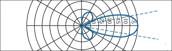
- Beamwidth. The 3dB beamwidth or Half-power beamwidth. is the angle between the two directions in which the radiation intensity is one half the maximum value in the center of the beam. Of course you can also have a 1dB beamwidth which is the angle between the directions in which the radiation intensity is 1dB less (79%) of that in the center of the beam. When the dB value isn't specified, usually the 3dB beamwidth is being used.
- Radiation efficiency is the ratio of how much power is delivered to the antenna feed to how much power is actually radiated by it. Power can be lost via mismatch, ohmic losses, feedline transmission losses etc. For a well designed system this number will be close to 1 (100%)
- Illumination efficiency. This is the fraction of the power radiated by a dish antenna to that which would be radiated if that dish was uniformly illuminated by the feed. For real world dishes this is always less than 1. Real world feed range in illumination efficiency from maybe 0.5 to maybe 0.8, with 0.65 being a typical value.
Of these parameters, the 3dB beamwidth is the easiest to independently measure with a reasonable degree of accuracy. Gain is hard to measure accurately, but can be inferred form 3dB beamwidth
The gain of a dish antenna can be estimated using the formula:
BW is the 3dB Beamwidth and
IE is the illumination efficiency
The factor of 52525 comes from the ratio of the number of square degrees on the inside of a sphere when views from the center, to the area covered by the beam of an antenna with which is 1 degree in diameter. It represents the gain you would get from an evenly illuminated dish (illumination efficiency=1). For a dish which is non-uniformly illuminated (i.e. all read dishes), IE is lower. If the edge illumination is -10dB, the IE could be as low as 0.5, though with some beam shaping it could rise to perhaps 0.65. For some specially shaped dished with exotic feed arrangements it can be even higher (0.8 to 0.9) but these are generally beyond the scope of amateur systems.
Measurement of Beamwidth and gain of a small dish
Below if a plot of sun noise vs. time for a small, 85cm offset fed dish on 10.368 GHz. Maximum sun noise is 7.15dB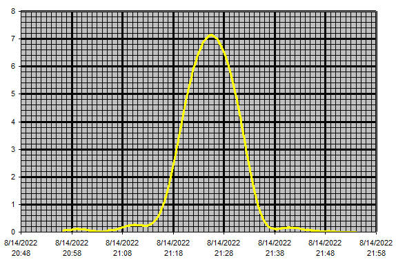
On the lower bands with lower gain Yagis, rather then letting the sun drift through the beam, it may be more practical to first measure peak sun noise, then calculate the expected reading when the signal drops by 3dB (see the next paragraph), the rotate the antenna until you see the predicted -3dB noise level. This is quicker and when the beamwidth is wide, accuracy isn't compromised. With very narrow beamwidths the drift method is better because the sun can move a significant fraction of the beamwidth in a short time, e.g between rotating the antenna to the left and right to get the -3dB readings
To find the -3dB points it's first necessary to calculate the reading which would be expected if the signal dropped by 3dB. Since the "sun noise" is a Y-factor measurements it measures (signal + noise) / noise, not signal/noise, so a 3dB drop in signal doesn't mean a measured Y-factor of 7.15-3 = 4.15dB. Using the graphs and/or formulae given in Signals and Noise, you can calculate that when the signal is 3dB down, the Y factor measurement will in fact be around 4.9db (not 4.15dB).
For the drift plot above, the time difference between the 7.9dB points is about 10 minutes. At the time this scan was taken, the change in elevation was ~0.18 degrees/minute. The change is azimuth was 0.167 degrees/minute, but this has be be corrected by the cosine of the elevation, which was around 22 degrees, which comes to 0.155 degrees/minute. So in the 10 minutes it took for the signal to rise and fall by 3dB, the moon elevation changed by 1.8 degrees and the azimuth changed by 1.55 degrees. The angular motion of the sun was therefore (via Pythagoras formula) the square root of (1.8^2 + 1.55^2) which is 2.375 degrees. So the 3dB beamwidth of the dish was ~2.375 degrees. If you are rotating the antenna (rather than waiting for the sun to drift through the beam) to measure horizontal beamwidth, you will have the azimuth readings directly and all you have to do is modify them by the cosine of the elevation.
[Note on the use of the cos(elevation) correction factor for azimuth. Consider the case of a 90 degree elevation. You can change azimuth by 360 degrees and you will still be pointing at an object with 90 degree elevation. Cos(90) is zero! At 45 degrees elevation the same effect occurs, but not as strongly. Cos(45)= 0.707. When elevation is zero degrees, there is no modification needed. Cos(0) = 1.]
Things can be simplified a bit if you do the measurement at transit, i.e. when the sun is at it's highest point, which will be when the azimuth is 180 degres and at local (solar) noon. Under those conditions there will be very little change in elevation, so only changes in azimuth (corrected by cos(elevation)) need to be considered.
Putting this into the equations relating beam width (2.375 degrees), gain and illumination efficiency, this gives an estimated gain of 37.8dB and an illumination efficiency of 65%, which is a typical value for a parabolic dish.
There's also a theoretical gain calculation which can be made based on dish diameter. For a dish of diameter "d" operating at a wavelength "w". the gain can be estimated as being:
Where k is the illumination efficiency. So for a 85cm dish at 10358MHZ = 2.89cm wavelength and an illumination efficiency of 0.65, you would calculate a gain of 10*log(0.6*(3.1416*85)/2.89)^2)= 37.4dB.
So the estimate from dish diameter and measured beamwidth are very close 37.4dB vs 37.8dB. In this case we can certainly say that the dish gain is probably 37.5dB +/- 0.5dB.
On 1296 the following sun-drift plot was obtained with the sun at an elevation of around 28 degrees at the sun noise peak.
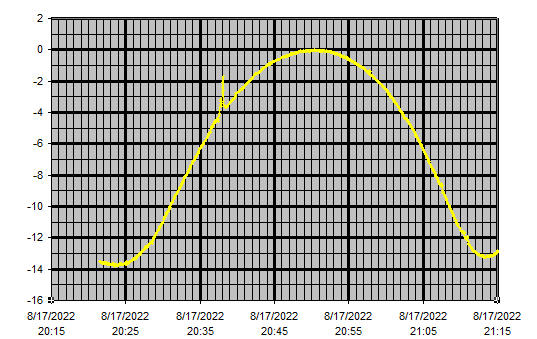
Analyzing this data in the same way as that for the 10Ghz data, basically looking for the angula distance through which the sun moved during the time between the -3dB points of the data, and taking into account the modification of the azimuth readings by the cosine of the Elevation and conversion of (signal+noise) to (signal), an estimated -3dB beamwidth of ~5.2 degrees was obtained. With an illumination efficiency of ~65% this would correspond to a gain of around 31dBi, which is close to what would be expected from the 3.1 meter dish being tested, confirming that everything is in pretty good alignment.
Yagis
For Yagi antennas, estimation of gain vs. physical size isn't really possible, so measuring the 3dB beamwidth may be the best way of estimating gain. It's hard to give an exact formula for all Yagi antennas, but something like the following will usually give a reasonable estimate. You may have to measure both vertical and horizontal beamwidth, especially with Yagi arrays having different numbers of antennas in vertical and horizontal stacking.
Looking at data in EMECack for Yagi gain and beamwidths it appears that the gain for a single yagi can be estimated by:
Where BW is the -3dB beamwidth in degrees. If the horizontal beamwidth BWh is different from the vertical beamwidth BWv, the replace BW^2 with BWh*BWv