.jpg)
KA1GT EME Page
Note that though much of this article is written in the present tense, It was written some time ago when I was operating on 432MHz EME. I am no longer active on 432MHz EME. In 2018 I moved up to 23cm using a dish. I no longer have the antennas and amplifiers for 432MHz EME operation.
I initially began working EME on 432MHz in the late 1970s. Around 1979 I built 16 8-element Quago antennas. They were simple to build. Wooden booms with aluminum director elements glued through holed drilled in the boom and copper wire loops for the driven element and reflector. One you have the technique down, you can build one in a hour, so you can build 16 of them an a few days! I also built a 2 tube parallel amplifier using 4CX250B tubes - the classic K2RIW design. The premap I built was based on a Plessey GAT-4 (I think) GaAsFET. A Microwave Modules 2m to 70cm transverter in conjunction with a Kenwook TS700 2m transciever was the heart of the station. I had to build a small 2C39 amplifier to to the output from the transverter up to the 30W required to drive the main amplifier.
Here's the only picture of the antenna array I could fine:
KA1GT 432 EME array, New Haven, CT. Around 1980. 16 x 8el Quagi Antennas
It was bolted to one leg of a triangular tower on the roof of the Engineering and Applied Science building at Yale University in New Haven Ct. Azimuth range was limited by the other two legs! It was manually aimers, so every 10 minutes I had to run down a corridor from my office, climb up a ladder to the roof, run over to the antenna, aim it by eye (visual moon required), then run back to the ladder, climb down and run back to my office. A somewhat awkward process!
Despite the system limitations and that fact that it was CW only (no WSJT in 1980), I made a a few dozen contacts during the period between about February 1980 and May 1981, including I5MSH, G3WDG, ZE5JJ, DL9KR, G3YGH, DL7TCA, K5JL, G3LTF, SM3GGF, KA0Y, WB5LUA, K2UYH, SM6CKU, W5FF and K3NSS. Quite a few of these stations (including me) are still on 432EME 36 years later! In mid-1981 I moved to work at Bell Labs in NJ and my QTH was surrounded by very tall trees giving me a very small moon window, so I didn't operate EME for the next 35 years....I did occasionally work tropo on 2m, 70cm, and 23cm though.
Then in 2014 I moved to Maine. Despite local antenna restrictions and a very small area in which to put an antenna, I did put up a 28el Yagai for the 2014 ARRL EME contest and with a 100W solid state amp lifer made a couple of contacts off the moon. When the moon is at +ve declination I can track it from moonrise on the horizon to within and hour or so of moonset, so the moon window is very good. At low declination it barely rises above the roof of the house. I was in hospital for the 2015 contest so didn't work anything that year...
In 2016 I got a little more serious. I added a second 28el yagai and resurrected my only K2RIW amplifier which had been sitting in a box for several decades. I used one of the old 4-way splitters from my original array, modified to a 2-way splitter, to couple the antennas. I got the old bias supplies working and built a new high voltage supply from scratch. It uses a toroidal transformer and it's rated for 1600v AC @ 500mA (120v primary). It has no problem delivering 2000v DC at 600mA run off a variac with around 125v on the primary. The premap is now a PGA-103+ GaAsFET MMIC. Not the greatest but local local noise sources prevent me from taking much advantage of a really low noise figure preamp. The PGA-103+ probably gives me a noise figure around 0.6dB, but the device is cheap and I can replace it in 30 minutes if I blow it up! Additionally the device is 50 ohms in and 50 ohms out so no matching or tuning is required. I have devices for a lower NF preamp but haven't yet gotten around to building one. I would gain a little, especially when the antenna is at one of the lower noise positions.
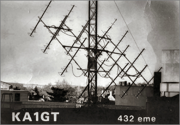
The current array is shown below:

KA1GT 432 EME array, Bar Harbor, Me. 2016. 2 x 28el (9WL) Yagis
Each Yagi can be rotated through 180 degrees by a small geared stepper motor behind the reflector element so I can control polarization. Maximum rotation speed allows a 180 degree rotation in about 6-8 seconds, which is fast enough to switch polarizarion between Tx and Rx periods for JT65B operation. The rotation for Tx and Rx can be set to different angles and can be automatically switched between to two to compensate for that fact that Faraday rotation is non-reciprocal between two stations. Each antenna can also be rotated independently for alignment purposes. The system isn't perfect. There's some antenna droop with long Yagis, so things are not in perfect balance all the time, butthe geared stepper motors have enough torgue to make the rotations. Some form of forward suppoet, similar to the rear cross boom would improve things.
The gain of this array is probably about 3dB less than that of my earlier 16x8el Quagi array, but back in 1980 I was running CW. Today I'm running JT65B, which more than makes up for the lower antenna gain and I can work a lot more stations (in much less time) today than I could back in 1980. The current antenna system is still manually aimed at the moon, but as of 11/16 I'm in the process of adding azimuth and elevation motors.
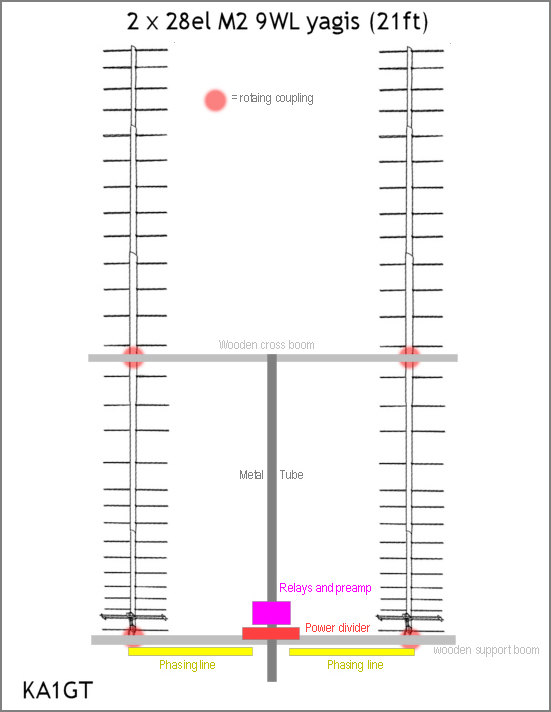
Basic layout of KA1GT 2 x 28el antenna
The array is mounted on an old roof tripod and the antennas can be removed in about 10 minutes and the whole system taken apart for storage (or transport) in about 30 minutes It's essentially a portable system, used only in my garden. It's taken down during bad storms and in the winter (Jan-Mar). It doesn't so well in high wind or heavy snow.
The old K2RIW amplifier just keep on running. When I initially fired it up after decades in storage it arced out of couple of HV feed through caps and blew up some resistors in the metering chain. However after several cycles of replacements (and a couple of boxes of fuses) it's now pretty reliable. Worked the whole 2016 EME contest without even blowing a fuse. For JT65B I run it at about 1.2KW in (2000v @ 600ma) and get somewhere around 550-600W out with ~30W of drive. Doesn't seem to mind running "key down" for 46 seconds. I could probably run it harder at the risk of blowing up a tube. Though it's biased into class C and should be giving me 70% efficiency, I've had trouble getting more than about 55% efficiency out of it. It normally runs at about 50% efficiency (assuming my Bird power meter is correct).
For a small system, handicapped by local noise, it does quite well. During the ARRL EME contest I made 26 FT65B QSO of which 15 were made in one evening. Bad weather limited operation on the other days. I believe one stations, LU8ENU, was running a "clone" of my station (2x9WL yagis and 500W) so JT65B contact is possible between two stations of this size. There were probably at least half a dozen stations that I think I would have been able to work on CW if I was set up for it. I normally have no problem detecting my own echo with a singe 2s transmission using WSJT-X echo mode. That's always my first "QSO" when I turn the system on. If I don't see my own echo, I look for something that's not working properly.
My local noise issues are unresolved at present. There are antenna positions and polarizations where sky noise is 3dB (or more) less than the noise from a 50 ohm load. There are also antenna positions and polarizations where "sky" noise is 3dB HIGHER than a 50 ohm load. That means I'm losing at least 6dB in receive sensitivity under worst case conditions. The stronger stations come though OK, but the weaker ones are lost. I'm in the process of mapping the noise in both position and polarization so I know what the best times will be for weak signal contacts.
In 2018 I will be changing over to a 2.4m dish for 1296 EME and I will also be fitting a 432 MHz feed to the dish and using it in place of the Yagi array described here. You can find more details on the KA1GT 1296 and 432 EME page.