.jpg)
10GHz Diode Detector/Mixer/Multiplier
[This article appeared in QST, March 1986 and is reproduced here with permission from the American Radio Relay League]
Author: Bob Atkins - KA1GT
A waveguide mounted diode detector/mixer/multiplier for use at 10GHz is both inexpensive and easy to
construct. It finds use in aligning filters, measuring power output, determining waveguide
VSWR, acting as a signal generator and even operating as a simple mixer and costs only a few dollars. A suitable diode is
one of the 1N23 series. Currently (02/14)
1N23 series diodes can be found on eBay for $5-$10. These are found with letter suffixes (eg, 1N23C), which denote the
diode noise figure, the lower noise figures being denoted by the latter letters of the
alphabet. A 1N23C has a noise figure around 9.5 dB, while a 1N23G typically measures
around 6.5 dB. In a diode detector, the noise figure is of no consequence, and so the
cheapest (or most easily found) diode is the one to choose. If the device is also to be
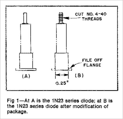
used as a mixer, then it is worth selecting a low-noise diode. The package outline of the
thin series is shown in Fig 1A.
To construct this detector, the diode is mounted across a short piece of closed-end waveguide, one quarter wavelength from shorted end as shown in Fig 2. One quarter wavelength, measured inside WG90, corresponds to about 9.5 mm at 10.368 GHz. In order to better match the detector to the waveguide, matching screws are inserted through the wall of the waveguide some distance in front of the diode. The distance between the diode and the matching screws is not important, but the distance between the screws themselves should be about wavelength/8 (5 mm in this case). Usually, with a three-screw tuner of this type, only one or two of the screws will be required to provide a good match, but three positions are needed since it isn't possible to determine in advance just which of the screws will do the matching.
There are many ways to mount a diode of the 1N23 series across a waveguide. Her's just one of them. First take a 3-inch length of brass waveguide and square off the ends with a file. Mark out a point in the center of the broad face of the waveguide exactly 9.5 mm from one end. Using a drill press or stand, if available, drill a 1/8-in-diameter hole through the waveguide wail at this point. Continue drilling through both broad walls. Open out the hole drilled in the opposite wail with a 1/4 inch drill. Clean up the holes and remove any burrs from inside and out-side the waveguide with a small file. If the waveguide section doesn't already have a flange attached, solder a flange on the end of the waveguide furthest away from the holes just drilled (see figure 2). A short length of the guide (< 1 mm) should protrude from the front face of the guide. After the guide has cooled, this should be filed back to produce a smooth face on the flange.
Next, cut out a 0.5-inch x 1.0-inch piece of brass sheet (any convenient thickness). This brass sheet is now soldered in place to close off the end of the waveguide closest to the holes. Try not to get any solder inside waveguide since any solder inside the guide will result in added loss (solder is more lossy than brass at 10GHz). About 2 inches from the closed end, mark out the positions for the three matching screws. These should be in the center of the broad face of the waveguide and 5 mm apart. Drill through the waveguide at these positions with a no. 50 (0.0700 inch) drill and tap these holes with a 2-56 tap. Using 2-56 screws (preferably stainless steel, which will not take solder), jig three 2-56 brass nuts to the waveguide over these three holes and solder them in position. Three brass screws with locknuts may be inserted into the three nuts until they are just flush with the inside wall of the waveguide.
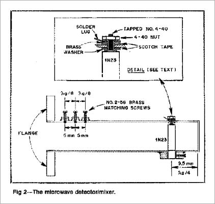
The diode should now be prepared for mounting. Carefully thread the brass pin on one end of the diode with a 4-40 die. Take care, or there is a chance of damaging the diode by twisting the end off. The other end of the diode is 1/4 inch in diameter, with a small flange. File off the flange to produce a uniform 1/4 -in-diameter end, as shown in Fig 1B. Next take two thin 4-40 washers and cover one side of each with a single layer of Scotch tape. These will be used to form a capacitor to decouple the output of the diode to the waveguide. The last part to make is a brass disk, about 1/4 inch thick, 1/2 inch in diameter with a 1/4-inch hole through its center and a set screw through the side. An alternative to making this piece is to take a plastic knob designed to fit a 1/4-inch shaft. Choose one with a metal center. A sharp blow with a hammer will remove the plastic, leaving a suitably shaped brass piece complete with a set screw! This brass piece is soldered to the bottom of the waveguide so that the 1/4-inch hole in the brass piece lines up with the 1/4-inch hole in the waveguide.
Take the diode and insert it through the 1/4-inch hole. With a pair of tweezers place
one of the insulated 4-40 washers, with the Scotch tape side up, over the threaded end of
the diode inside the waveguide. Push the diode up so that the threaded end pokes through
the hole in the top of the guide. Place the second insulated washer, Scotch tape side
down, and a small solder lug over the threads. Screw on a 4-40 nut and tighten it down.
Make sure that the diode is centered in the hole in the waveguide and that it is not
shorting to the wall. Tighten up the locking screw on the mount on the bottom of the
waveguide. The detector/mixer is now complete. If you attach a meter to it as shown in figure 3 and inject a low power 10GHz signal,
you can match the detector by adjusting the three tuning screws for maximum diode current.
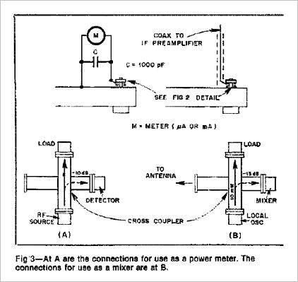
Figure 3 shows some suggested configurations of the mixer/detector using a waveguide cross coupler.
The detector/mixer can also be used to generate a low power marker signal on 10GHz by applying RF to the diode. You can drive it at 48MHz, 96MHz, 144MHz, 432MHz or 1296MHz to produce a signal at 10368GHz. While the 1N23 isn't really the best diode for this purpose, it will work. RF power to the diode should just be enough to give a diode current of around 20-25mA. RF out will depend on the degree of multiplication. the higher the drive RF frequency, the higher the output at 10GHz. Optimally driven at 96MHz I've seen reports of about -45dBm output at 10368MHz. -45dBm is 0.000032mW or 0.032 uW. not much power. However, in theory, with an optimized system and very good receivers (3dB NF) and a 300Hz bandwidth, a 100 mile line-of sight path might just be workable.