.jpg)
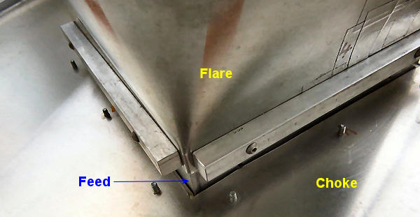
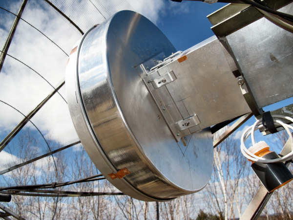
1296MHz Septum Feed with Flare and Choke
The latest incarnation of my 1296 EME system uses a newly constructed septum feed with a square to circular flare and a choke. Used with my 3.1m mesh dish, which has an f/d ration of around 0.34 and a G4DDK preamp with a noise figure which is probably in the 0.26dB region, I see around 12.5dB sun noise from the quiet sun.
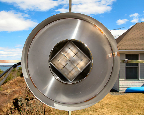
Looking right down the axis of the feed
The feed waveguide is 6" square aluminum tubing (1/8" wall thickness) and the septum and back wall were cut out of 1/4" thick aluminum plate. The flare is made from aluminum flashing and the choke started life as an 18" cake pan! Here's a picture of the septum feed parts parts before assembly:

The basic feed is based on a feed described by KL6M, which is in turn based on the original design by OF1DFC. I won't go through all the details of construction. It's essentially the same as KL6M details in his paper, but with some difference in the placing and number of the bolts that hold it all together and slight differences in the feed probes and tuning disks. Nothing very critical, I just used materials on hand and convenient placing for the fasteners.
Construction isn't difficult, but it can be time consuming making sure all the dimensions, hole placements etc. are accurate, the holes in the three parts line up and the parts fit together well. A mill helps, but the parts can be made using little more than a hacksaw and file (and a few days of your time). A drill press is very useful to get accurate positioning of the clearance holes and tapped holes for assembly. There are a lot of holes. Use a high quality tap (preferably not purchased from China at a bargain price via Ebay) for the 4-40 thread cutting, treat it with care and use the proper techniques for tapping. You do not want it breaking-off half way through the projects.
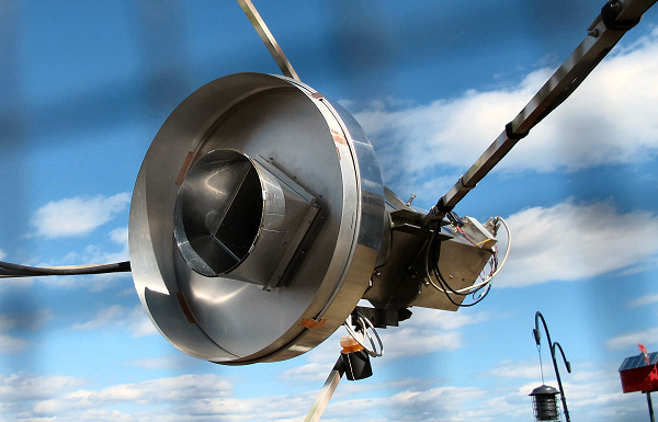
Feed as viewed through dish
I won't go into details of how to tune the feed. KL6M covers that in his article at the link above. You can certainly set it up on the bench for maximum return loss (minimum SWR) at 1296 on both the RX and Tx ports, and you can measure isolation, but as soon as you mount it on the dish, things will probably change a bit (especially isolation, which may change a lot) because of the signal reflected from the dish and back into the waveguide. If you can tune things on the dish, that's good. If not you can probably tune the Tx port for the best SWR. Rx port could be tunes by looking at sun noise and tweaking for a maximum, though I've found that tweaking the Rx port seems to make little difference if you are close to start with. You could get close by coupling power to the Rx port and tuning for best SWR.
The Flare
Why use a flare? Well, I've been playing with flares for a while (see "GT" Flare for OK1DFC 23cm Septum Feed). The ideas behind the flare are simple:
(1) - A flare can be used to modify the beam profile from the waveguide aperture. Basically, the larger the opening of the flare, the narrower the beam profile will be. So by adjusting the size of the flare aperture, you can, in principle, tailor the illumination angle of the feed.
(2) - Square waveguide does not produce a particularly "clean" pattern. The corners tend to generate unwanted effects on sidelobes, polarization etc. Ideally you'd want a circular waveguide. The square shape of the OK1DFC septum feed is more for convenience of construction than optimization of the feed characteristics. It you are going to make the feed at home out of aluminum sheet metal and screws, it's a lot easier to do it with square geometry.
On the basis of the information given in the page here on Dish Illumination, the OK1DFC design septum is already a pretty decent match for a dish with an f/d of around 0.34. See also W1GHZ's paper on Enhancements to the OK1DFC septum feed. Consequently the flare doesn't really need to much in the way of narrowing or widening the feed beamwidth. When it comes to cleaning up the pattern, W1GHZ has looked at the effects of square and octagonal flares . He found that a square flare didn't work very well, but an octagonal flare was better. Logic suggests that if octagonal is good, circular would be better. I believe the exact geometry of a square to circular transition is rather difficult to model and he didn't look at such flare geometry. See also W1GHZ's article Electromagnetic Fields in Feed Antennas
What I did was make a few rough calculation of what I wanted, which seemed to suggest that not much change was needed in the feed beamwidth. So I put the calculations to one side and decided to go with the old "try the easy way first" solution. Basically, if you take a cylinder made out of thin aluminum (fairly easy to make with aluminum flashing and duct tape), which has a circumference equal to the sum of the sides of the square waveguide (6" square, so 24" in total), you can deform one end into a square and fit it around the waveguide. It's 6" square (0.66λ) at one end and 7.64" (0.84λ ) in diameter at the other and it's very easy to fabricate. How long should it be? Well, not too short, but not too long. A side taper angle of 10-15 degrees is usually OK for a flare, so I made this one a cylinder that was 4" long. That gives a maximum taper angle at the sides of the square of around 11.6 degrees. At the corners, the "flare" actually slopes inwards by 5 degrees.
Blue - the 6" square wavequide (6" on each side); Red - the flare aperture (24" in circumference)
Getting a good fit to the waveguide with a minimum gaps and good electrical connection is left, as they say, as an "exercise for the reader", but here's a picture that illustrated what I did. It basically involves more cutting, drilling and tapping.
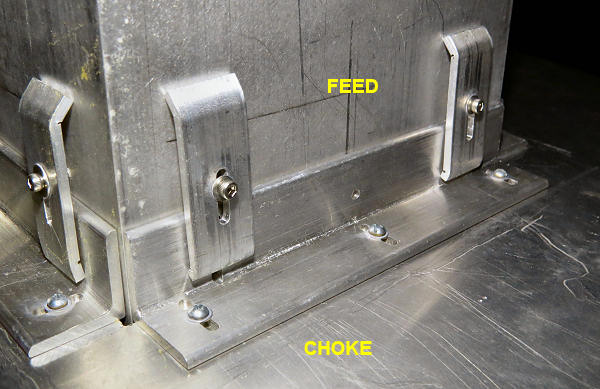
Flare to Feed clamping
Here, four ~5.8" long pieces of square aluminum bar stock attach to threaded holes drilled in the sides of the waveguide. The square end of the flare is sandwiched between these bars and the outside of the waveguide, holding them in place with good electrical contact.
The Choke
The idea of the choke is that it takes energy that would normally flow back down the outside of the feed (giving rise to lost power and a sizable rear lobe) and redistributes that power by a sort of "parasitic" radiation from the aperture of the choke. If the dimensions are right, that power combines with the power from the feed aperture with the correct phase so that it reduces side and rear lobes and directs more energy towards the dish with a desirable power distribution. I'd guess this explanation would not sit well with professional RF engineers, but it's a reasonable way to think about what's going on. The trick with chokes is getting the width, height and position relative to the waveguide aperture exactly right so that you get the effect you want. If you get any of the dimensions or position wrong, the choke can have a negative effect, making dish illumination worse and sidelobes stronger. The best way to deal with this as a home constructor is to (a) read the literature on chokes, especially modeling studies by W1GHZ, and (b) make it as adjustable as possible so that you can mechanically change the critical dimensions and position in order to optimize things by experiment. Adjusting for maximum sun noise for example.
The choke itself is roughly the size and shape of a large cake pan - so a large cake pan is, in fact, the easiest thing to make a choke from. There aren't a lot of choices here. Basically the choice is an 18" diameter cake pan that's 3" deep. That's pretty much all there is that's close to the right dimensions, so that's what you use. You can find such cake pans on-line. Try these two links (which are good as of 05/20):
https://www.sweettreatsupply.com/Round-Aluminum-Pan-18x3-p/3163.htm
https://www.wineandcake.com/fat-daddios-18x3-round-cake-pan.html
To turn the pan into a choke you hack a 6" square hole out of the center and it will slip over the waveguide (though NOT over the flare, so the order of assembly matters!). More cutting, drilling, slotting, tapping and clamping (this using aluminum angle stock) will enable it to be attached it to the waveguide as shown below:
Choke to waveguide clamping
Choke depth is 3" because that's what you bought and that's the maximum depth 18" cake pans. However you can make it deeper by inserting a short cylinder of aluminum inside it. Note that the walls of the cake pan may not be exactly at right angles to the base. Why? Well it's probably easier to get the cake out is the pan if it's slightly larger at the top than at the bottom, so you have to deal with that.
The above image shows the depth extended by a few cm. Getting good electrical contact is probably important. You could resort to more drilling, tapping and screws, but (at least for a temporary fix) you can try using copper (or aluminum) tape with conductive adhesive. This is sold for RF screening applications. The adhesive isn't VERY conductive, but it seems to work.
Once you have everything assembled you can use sun noise to optimize the choke depth and position. This will give you the best Rx performance (which may be different from the best Tx performance). An hour of so of tweaking should be enough to find the best position. For MY dish, which will no doubt be different from YOUR dish, I found a total choke depth of 10.65cm (0.46λ) with the rim of the choke 1.6cm (0.07λ) behind the flare aperture worked best for me based on maximum sun noise (best Rx performance) - which is what I was looking for. The choke position could slightly affect where the phase center of the feed is located, so check the effect of moving the whole feed back and forth when you think you hve the choke in the right place. Then you could check the choke position again if you haven't gotten tired of making adjustments.
Note that there is an argument against using a choke because it does result in additional feed blockage. Is the beneficial effect of the choke cancelled out by the fact that it blocks some of the signal from reaching (or leaving) the dish? For a very small dish the answer is possibly yes, while for a large dish the answer is certainly no. Chokes can certainly be effective on dishes as small as 1.9m. I don't know any tests on dishes smaller than that, though there comes a point at which a Septum feed gets very large and heavy compared to the dish itself. At that point maybe a small, lightweight patch feed is something to consider. They work quite well, though are more complex, requiting addition relays and 90 degree hybrid coupler for circular polarization and T/R switching.
Does it work?
It seems to. On avenge I'm typically seeing something like 12.6dB of sun noise on the quite sun (SF<70). Of course sun noise is influenced by the preamp NF, plus losses ahead of the preamp (relay, connectors, cables) as well as the characteristics of the dish (gain, spillover, sidelobes) but 12.6dB is fairly good number for a 3.1m dish so I think the feed must be working reasonably well. Could it be improved with a better feed design? A different flare? No flare? A different choke? The answer is probably yes. Maybe another 0.5dB could be squeezed out of it with a better design and better optimization, I don't know. Echoes with around 240W at the feed and the moon at perigee now measure between -6 and -7dB using my own software specifically for echo measurements (I don't use WSJT or WSJT-X for echo measurements - I don't find them accurate or reliable). I do know I'm reasonably happy with my system performance and probably won't be building another 1296 feed anytime soon!
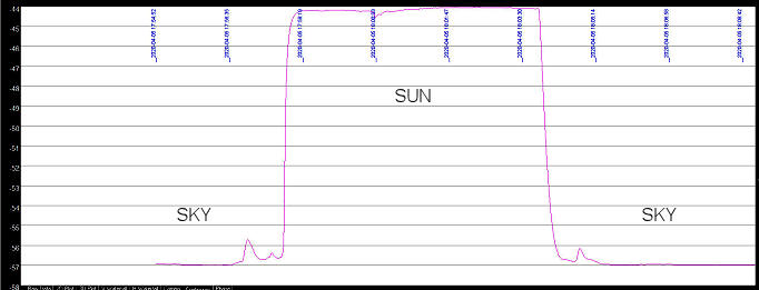
This test showed very close to 13dB of sun noise). The best I've seen (-10C outdoors) was 13.1dB.
Is a flare and a choke "better" than just using a choke? I don't know because I haven't done the tests and as far as I know nobody has modeled it. It also depends on what "better" includes. Gain, sidelobes, Xpol? Is just a flare better than just a choke? Again, I haven't done the tests. Is a flare better than nothing? I think the answer is that it can be. I did some tests with another feed and flare that suggested it could result in better performance if it was the right size and used with a dish with an f/d not well illuminated by the bare OK1DFC septum feed. Modeling by W1GHZ (Septum Polarizers and Feeds) also suggests that an octagonal flare could improve the performance of the OK1DFC feed under some circumstances (e.g. with f/d ratio of 0.5-0.7)
Other Reading
There's an interesting feed design by RA3AQ which consists of a round extension to a square septum polarizer and includes a choke. In some ways it's similar to the flare plus choke feed I described here, but it has an abrupt step to a circular aperture of 206mm (vs a flare to 194mm) and the choke is deeper (146mm vs 106.5mm). It was modeled by W1GHZ who found it had excellent performance.
The are some rectangular flare designs from OK1DFC at Flare for Septum polarization feed and Flare for All Bands. These are designs for rectangular flares to make the original OF1DFC septum feed more efficient with dishes with f/d ratios of 0.5 and 0.7. They do not include the use of a choke.
Caveat
What works for me may not work for you. Don't take these numbers as "carved in stone". You have to tweak things on your own system to get the best results for your equipment. If your dish doesn't have an f/d around 0.34, it's unlikely my numbers will be optimum for you. I'm not suggesting you go out and build this feed, I'm just reporting what I did and what the results were.