.jpg)
Dish Evaluation
...well it's big enough but the f/d ratio looks a bit off...
So you have a dish antenna and you want to know how good it is. How do you test it?
There are several test you can do. Some involve only the dish itself, while others involve the Rx system.
- Physically measure the profile of the dish and compare it with the calculated profile for a parabolic dish of the same diameter and f/d ratio. This does not depend on anything but the dish itself
- Measure the beam profile of the antenna. This is also related to the dish feed characteristics. A beam profile that's wider then predicted could be the result of a dish profile that isn't parabolic.
- Measure Sun Noise. This also depends on the feed characteristics and the system noise figure. A poor profile will result in lower then expected sun noise - but so will the use of mesh material with holes which are too large for the frequency in use.
- Measure Echo strength. This also depends on the feed characteristics, the system NF and the accuracy of pointing. A poor prifile will result in lower than expected echo strength - but again the use of a mesh surface with holes which are too large will also lower echo strength.
Measuring the dish profile
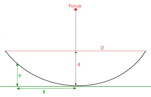
To measure the profile of a dish you need to make a series of simple measurements. These include the width of the dish (D), the depth of the dish (d) and a series of measurmentst of the height of the dish (Y) at a series of positions (X) from the center to the edge. You can equally well measure the depth of the dish at a series of positions oron the center to the edge, and in fact this may be easier and more accurate since you can measure to the front surface of the reflector (which is what counts). These measurements are shown in the figure below.
Using an online tool like Parabola Calculator 2.0 you can calculate what the shape should look like, once you know the depth in the center and the diameter. You can then compare your measurements with those of the parabola calculation and see how close they match. If the dish is well profiled for the frequency in use, the surface error should be no mare the +/- 1/10th of a wavelength, e.g. +/- 2.3mm for 23cm. Ideally, to realize the full potential of the dish, it should be better than this, perhaps better then 1/20th wavelength (about 1/2" at 1296). The very best microwave dishes have surface accuracy of 1/40 wavelength.
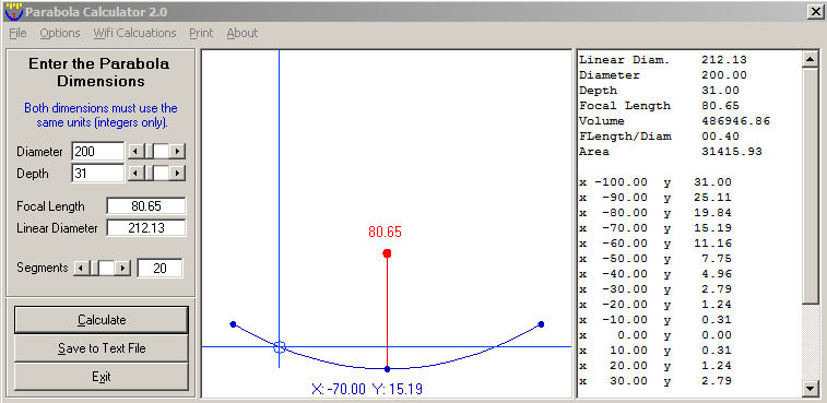
It's difficult to predict exactly how surface accuracy will affect gain since it's not only a function of the magnitude of the errors but also their distribution across the whole dish surface and the spacing between the high and low areas, but if you are within 1/10 wavelength, the loss of gain shouldn't be more than around 1dB.
Beam Profile
Note that the following analysis assumes that the 3dB beamwidth of the antenna is significantly (>2x)larger than the diameter of the source (typically the sun angular diameter is about 0.5 degrees). Corrections are required for large dishes operating at the higher frequencies. A 1.2m dish at 10Ghz has a half power beamwidth of around 1.6 degrees, so estimates of beamwidth based on sun noise measurements is reasonably accurate. However a 3m dish on 10Ghz has a 3dB beamwidth of around 0.6 degrees and this will result in antenna beamwidth estimates that are about 20% high
The beam profile can be measured using sun noise. You can either let the sun drift though the center of the bean with the antenna stationary. Alternatively, if you have accurate tracking and you can offset the antenna in small steps from the target, you can take a series of readings of sun noise vs. antennas offset and those those values. PstRotator can do this, with 0.1 degree tracking accuracy and 0.1 degree resolution offset - of your rotor system is capable of 0.1 degree steps.
There are two non-obvious factors to take into account here. One is the conversion of the ratio (Signal + Noise) readings (Y-factor readings) to yield difference in signal strength. S+N is not the same as S (see Signals and Noise. Just as an example. if you see a change in sun noise from 8db tp 5dB, that's not a drop in signal of 3dB. It's a drop in (S+N) by 3dB (3dB Y-factor). A 3dB drop in signal at a (S+N)/N of 8dB would give you an (S+N)/N of 5.64dB. This is explained on more detail in the reference just cited.
The second correction is related to the angular change in antenna position not being equal to the change in azimuth angle when the antenna is elevated. You can thin of it in this way. When the elevation is zero degrees and you move the antenna from an AZ of 90 degrees to an azimuth of 270 degrees, the antenna sweeps across a large angle in the sky (on the horizon). If the antenna is elevated to 90 degrees (pointing straight up) and azimuth is changed from 90 degrees to 270 degrees, the antenna stays pointing at exactly the same spot in the sky (the zenith). To get the true angular change in position in the sky for an elevated antenna, the true angular change is given the the cosine of the change in azimuth. So for an antenna at 60 degrees elevation, a 10 degree change in azimuth reading produces only a 10*cos(10) = ~1 degree change in angular position in the sky.
Taking these two factors into account, you can measure sun noise (either thy the drift method or the offset method) and plot the results (angular offset vs signal strength) and you will get a plot looking something like the one shown below:
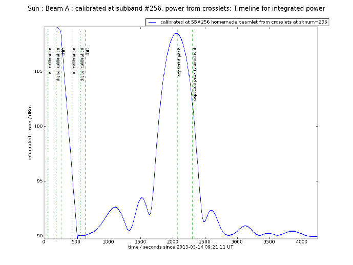
Figure from https://www.researchgate.net/publication/297738830_Characterization_of_a_dense_aperture_array_for_radio_astronomy
What can you tell from this? Well, the pattern is fairly symmetrical (though not perfect). Sidelobes on the left are slightly stronger than those on the right, but it's not bad. In the case if a dish, this could indicate a slightly asymmetric feed or a feed that was slightly off center.
Here's an example of the effect of dish distortion on the beam profile:
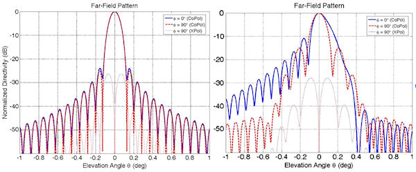
Figure from Subreflectarrays for Reflector Surface Distortion Compensation
In this case it's pretty clear there is a problem that needs to be corrected! Gain loss here was 3.3dB.
What can you tell from this? Well, the pattern is fairly symmetrical (though not perfect). Sidelobes on the left are slightly stronger than those on the right, but it's not bad. In the case if a dish, this could indicate a slightly asymmetric feed or a feed that was slightly off center. The other thing you can tell (with a bit of work) is the antennas gain, prom which yo can calculate the aperture efficiency of the dish. For a typical dish with a good feed, you can expect an efficiency somewhere around 65%. The antenna gain is related to the beamwidth at the -3dB points by several a simple approximations - which assume no feedthough of the dish (if mesh) and no resistive losses.
Effect of mesh size for mesh dishes
Note that it is possible to get a dish with a narrow beamwidth and yet low gain if the holes in the mesh surface are too large, or if the whole thing is built using some sort of high resistance material resulting in high ohmic loss (not this is very unlikely to happen). For a mesh dish the holes in the mesh should be less than 1/20 wavelength if you want to keep addition loss under about 0.25dB. For Circular polarization, the diagonal distance across the holds in a square meesh is important. For linear polarization aligned with the direction of the mesh, it's the distance between the sides of the square holes that count. For i/2" mesh with 1mm diameter wires at 23cm with circular polarization this result in 0.2dB loss of gain (0.4dB for thinner, 0.5mm wires). Nominal 1/2" hardware clothe (Home Depot) on a dish would result in a loss of gain compared to a solid dish of around 0.185dB and an increase in noise temperature of about 6K. With 1" mesh this increases to a gain reduction of around 1.8dB with 1mm wires and 3.7dB with 0.5mm wires. This gain reduction won't change the beam profile, so you'd get the same 3dB beamwidth as you would with a solid dish, but with several dB lower gain. So in that case, the beam profile could look good, but sun noise and echoes would be lower then expected.
Effect of paint or other covering of the dish surface or wires
The resistivity of the surface (or mesh) isn't of much importance for normal materials. Whether it is steel, aluminum or copper, the gain difference will probably be too low to measure. However if you painted the surface with "stealth" RF absorbing paint, the gain would drop significantly (but the 3dB beamwidth would be unchanged). Most non-metalic paint won't have much effect, though affects have been seen in some studies, depending on the frequency in use, paint thickness and paint type. The best advice is probably not to paint the reflecting surface of a dish (solid or mesh), or to cover the bare metal in any way, especially if it is intended for use on the higher microwave bands. Then there's nothing to worry about! Large radio astronomy dishes and DSN network dishes are often painted (usually white) and use a special 500FHR6 acrylic urethane-based paint.If you want to know more about the math and physics behiand these approximations here are a couple of references to look at:
Bottom line
The point here is that for a given dish, e.g. a 2.4m dish on 1296, you can predict that the 3dB beamwidth is likely to be somewhere between about 6 degrees and 7 degrees, depending on efficiency, feed pattern etc. If you see a 2.4m dish with a 3dB beamwidth of 8 to 10 degrees, something is wrong, and what's likely to be wrong is that the dish does not have an accurate parabolic profile and/or there is a problem with the feed. e.g it's is in the wrong position The gain of a good, properly illuminated, 2.4m dish at 1296 MHz should be somewhere in the 28-29dB range. If the profile is good and the 3dB beamwidth if right, then low gain could indicate that the dish surface isn't suitable for the frequency in use.
Sun Noise
A measurement of Sun Noise tells you something about your overall Rx capability and is related to dish gain, feed pattern and system noise figure. If Sun noise is lower than expected (compared to other similar stations or calculations using EMECalc), then without further testing you don't know if you have an inefficient dish or a poorly performing Rx system. However measuring sun noise is a relatively simple process and so is always worth doing. For more on measuring sun noise see:
With 10.7 solar flux at around 130, a good systen with a 2m dish might show up to 12.5dB sun noise. With a 2.4m dish, 14dB and with a 3m dish maybe 16dB.
Echo Testing
The strength of your own echoes, like sun noise also depends on dish efficiency as well as Rx system performance. However it's particularly sensitive to dish gain (and pointing) since the dish gain factors in twice when calculating echo strength, one on Tx and once on Rx. A badly performing dish will be twice as bad on Echo testing as it will on measuring sun noise. Echo testing is also quite quick and easy, so again it's always worth doing. For more on Echo testing see:
A well optimized Rx system with a 2m dish and 100W at the feed should give echoes in the -17 to -19dB range (perigee/apogee), For a 2.4m dish that would be more like -14 to -16dB and for a 3m dish, -10 to -12dB