.jpg)
Offset to Prime Focus operation on 10Ghz.
In the fall of 2022, thanks to help form W1GHZ, I acquired a 1.2m prime focus dish to replace the 85cm offset fed dish which earlier articles here have described. I was initially a little concerned about properly feeding this dish as the old offset dish had and f/d ratio of somewhere around 0.6 and the new PF dish has an f/d ratio of 0.375. Therefore my old feed would not be a good match for the new dish (though it turned out not to be as bad as I thought it might be!).
For this system I changes from using the Avenger KSC321S-2 LNBF to the X-square IT-01 for reasons mostly related to availability. I doubt that performance is significantly different, they are both based on the same type of circuit and devices. They both start out with a 25MHz crystal oscillator (which needs to be replaced with an external high stability of similar frequency). This is all explained on a previous page. On this page I'll just outline the differences and provide some essential information, but it's not a "step by step" guide to building the modified feed.
The X-square IT-01
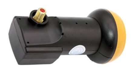
These are available via Aliexpress (e.g.https://www.aliexpress.us/item/2251832676143782.html. They are similar to most other universal LNBFs. My advice would be to buy more than one because they are cheap and there's an excellent change you may screw something up the first time you try to modify one! The black plastic housing is held together by snap connectors, so you just prize it apart and remove it. The front cap just clips on, but getting it off can be quite a struggle. It's on there tight. The output connector is an F connector. Note that unlike some other LNBFs, the front probe (the one upi want to use) is activated at around 16-20V, not 12v. The front probe is also at right angles to the F-connector, so when the F-connector is vertical, the front probe will give you horizontal polarization.
Note that there's nothing particularly special about the performance of this LNBF as far as I know. You can probably use any similar modern LNBF if you can figure out how to get it open and where to inject the external high stability reference signal. Most current LNBFs are controlled by a simple 25MHz crystal (old designs used a Dielectric Resonance Oscillator). One you get the LNBF open, the crystal should be obvious. You remove it from the PCB (possible easier said then done...) and there will be two terminal pads. You then inject a few mW at the reference frequency (somewhere near 25MHz). If it doesn't lock up when connected to one pad, try connecting it to the other pad!
Replacing the Crystal oscillator with an external reference
The internal 25MHz crystal in the unit as purchased will not be stable enough, especially in an outdoor location. You might find times when it's stable enough over 60 seconds to decode a transmission, but you might have to wait a while before you get one. Normally you'll see the signal; drifting back and forth at a rate that makes decoding impossible.
Below shows where the reference oscillator signal is coupled to the LNBF circuit board. A few mW at around 25MHz is needed. 25MHz gives you an IF at 618MHz, 25.4MHz gives you an IF at 462MHz (within the Rx tuning range of some 70cm transcivers), 25.4767230762307623MHz gives you an IF at 432MHz and so on. The IF is at 10368 - (390 * Reference Frequency). It will not lock for 1296MHz and the IF gain is too low at 144MHz, so if you need the IF in a ham band, it has to be 70cm. You can generate the reference signal in many ways. An indoor analog TCXO at 25MHz is probably quite useuble (though may show some drift), and that's fine if you can tune an SDR to 618MHz and get the audio into WSJTX for decoding. You can use a FunCube pro+ SDR with MAP65 to see and decode the JT65 and Q65-60 signals (such is the DL0SHF beacon). I have generated an LO signal near 25.476923 MHz using an Si5313 clock generator ($3.50 from China via Ebay) in conjunction with an Arduino microcontroller ($5 from China via eBay). This put the IF near 432 MHz. You can also use the Si5313 with a OCXO at $15 10MHz (rather then the standard 25MHz) which gives high stability. 25MHz OCXOs are available, but are harder to find and probably 5x the price of 10MHz OCXOs. You could use a 10Mhz GPS disciplined oscillator as the Si5313 reference, though you are probably adding at least $75 to the cost.You can also use a commercial GPS locked frequency synthesizer, but then you are adding maybe $200 to the cost.
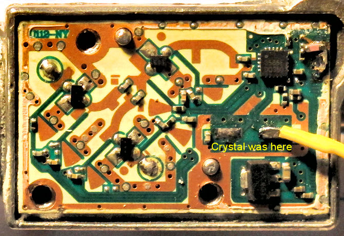
Just like before, the 25MHz crystal is removed - NOTE: WARNING: This is much easier said then done. The 25MHz crystal does NOT want to be unsoldered. There's a risk of actually pulling the pads off the PC board if you put too much force on the crystal and you have not got the solder pads hot enough (don't ask me how I know this....). If you do pull the pads off the board and you are lucky enough not to break the trace that connects them to the PLL/mixer chip, you can epoxy them back down with something like JB-Weld (quick), and you can still solder to them later. Again, don't ask me how I know this... If you break the trace to the PLL/Mixer you are going to have a very hard time re-making that connection. You have been warned.
The reference signal (few mW) needs to be connected to the crystal pad closest to the edge of the board. There's no convenient place to mount an SMA socket directly on the LNBF housing, so you have to bring out a wire through a small hole (or cut-out) in the LNBF cover, then mount an SMA connector on a small bracket as shown in the figure. The reference signal should be coupled in though a 1000pf capacitor (not a critical value) somewhere in the connection between the source and the LNFB.
Modifying the feed for use with a prime focus dish
To better match a prime focus dish with an f/d in the 0.35 to 0.4 region (which is typical of most small prime focus dishes), a short circular waveguide extension with a choke can be inserted into the existing LNBF feed. This feed is described my SM6FHZ. On page 110 of http://www.2ingandlin.se/A%20novel%205%20step%20septum%20feed%20suite_PF1.pdf he shows a circularly polarized septum feed for 10Ghz. Just ignore the septum and use the dimensions for the choke and it will work fine. For the waveguide, I used a short 3/4" copper pipe coupler which has in ID of around 22.2mm (see e.g. Home Depot)
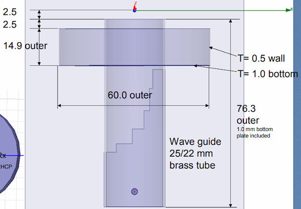
Above is a figure from the above SM6FHZ paper, which includes a septum polarizer. In this case all you are interested in are the dimensions of the circular waveguide and choke assembly. You don't need the septum plate and the overall length is not critical.
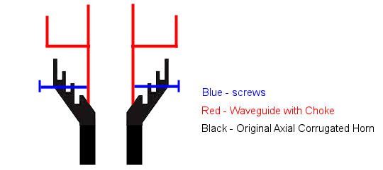
Above is a schematic of the conversion. A section of circular waveguide (~ 22mm ID), with a choke attached - shown in RED - is inserted into the original feed horn (shown in BLACK). Screws (shown in BLUE) can be inserted in from the side, though holed drilled and tapped in the original horn, which will hold the waveguide extension in place. Ideally you'd like the best possible contact between the original feed and the waveguide extension, but my experience is that just a push contact fit is good enough. Other schemes are possible to attach the waveguide to the feed, but this is the simplest and it works. Some of the original feed can be cut away is desired or if it interferes with the choke ring.
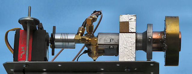
Here's a picture of the modified feed. In this case part of the original feed has been cut off, but this is not necessary. The phase center is a few mm in front of the end of the waveguide, and this should be at the focal point of the dish.

The feed extension with the choke is just pushed up against the inside of the original feed and secured in place with the set screws as can be seen in the picture above. Ideally you'd like to make good electrical contact at the point where the end of the extension meets the inside of original feed, but this is an aluminum-copper transition and so can't be soldered (at least not by me!). Though just pushing the two surfaces together isn't going to give a perfect contact all the way around the WG, it appears to be good enough. There are more complex ways of bolting the parts together so that they are in compression, when I tried this it didn't seem to make any difference.
Performance
Here's a sun noise measurements made on the 1.2m PF dish with the new modified LNFB and an SM6FHZ designed 10Ghz feed after tweaking everything for maximum sun noise.
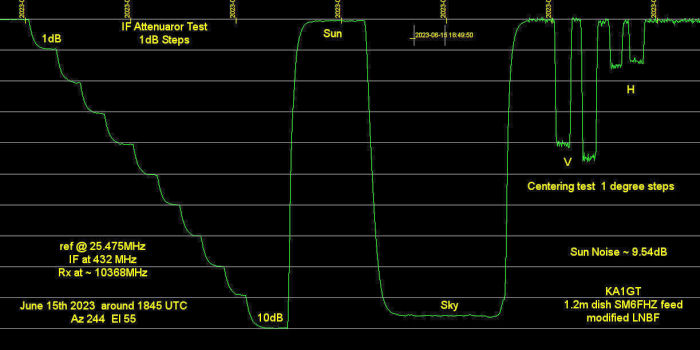
The reference frequency was set to 25.475MHz which generated a 9935.25 local oscillator frequency in the LNBF. This downconverted 10368 MHz to 432.75MHz. On the left are some 1dB calibration steps created by using a step attenuator in the 432MHz IF line. Then there are sun and sky noise measurements, followed by some offset centering measurements to make sure the sun really was centered (these were also done before the test started of course. Measured sun noise was around 9.5dB. These measurements were made using a FunCube SDR along with SpectraVue software. You can do essentially the same thing with WSJT-X in echo mode, monitoring the noise level column in monitor mode. Results should be the same if you have the FunCube gain set so that it's not going into compression with sun noise. You may get slightly different numbers if you use a lower reference frequency (which gives you a higher IF frequency), but they should be somewhere in the 8.5-9.5dB range, depending on your setup and how active the sun is on the day you measure sun noise. On air tests with DL3WDG indicated that Q65-60D transmissions decoded easily but it's hard to give an SNR value for the Q65-60E decode because the beacon power sometimes changes when it has a problem and gets repaired! After the latest repair to the driver amplifier (July 2023) I'm seeing decodes around -10/-11dB, but I believe the beacon is running at around 3dB lower power than it was earlier in the year (May 2023) when I was seeing decodes at -7dB. I believe current (July 2023) power is around 20W.
This performance is on a par with much more expensive 10Ghz transverters, even some of those with preamps. One reason is that this RX only modified LNBF system requires no relays ahead of the preamp and no coax to waveguide adaptors. Also, it's small an light enough that it's pretty easy to rotate the whole LNBF unit to match the polarization of signals off the moon, which can change by as much as 90 degrees during a moon pass. stations working each other in Europe can just about afford fixed vertical polarization since they are often geographically close and DPOL values are small. However DPOL values can be large and variable between stations in Eurpoe and North America. In my opinion, specially with a small dish, polarization rotation is a must for 10Ghz. For example from my QTH, Dpol can start out at around 0 degrees at moonrise, rise to a maximum of almost 90 degrees and on to +30 degrees as the moon sets for DL0SHF. A polarization difference of 45 degrees results in 3dB loss. 90 degrees give you theoretically infinite loss, but in practice it more often more like ~15dB.
Feed rotation. A servo motor rotates the feed +/- 90 degrees