.jpg)
Low cost 10Ghz EME Rx System
NOTE: This is not intended to be a definitive "how to" article, but may serve as a guide for those interested in receiving 10GHz EME signals at minimum cost and complexity.
Why 10Ghz
Several reasons. First, low cost commercial equipment designed for TV satellite reception is available. Second, there's a reasonable amount of EME activity compared to the other bands above 1296MHz. Third, there's a beacon - DL0SHF - which (when it's operational) can easily be received by this simple system. Fourth, most of the world uses the same frequency allocation so most of the activity centers on 10.368 GHz. Japan's allocation is different though and they are on 10.45Ghz. That's still a lot better then the situation on 13cm. Fifth, you can see/hear/decode signals with a very small dish. Dish diameters under 3ft will work quite well and receive quite a lot of 10Ghz EME signals.
So what's the low cost system
There are three options at outlined below. Each step is a little more complicated (and expensive) then the previous one
Stage 1 - An unmodified LNFB, An RTL-SDR dongle and a small (~1m) dish
Total cost here is around $35 plus the dish. Assuming you are pointed at the moon and you are running SDR software that controls an RTL-SDR dongle, you should be able to see sun noise and if you look at 618MHz +/- 0.5Mhz and you may see 10Ghz EME signals on the waterfall plot if any strong stations are active. You won't be able to decode any digital signals, but there is a small chance you may be able to copy CW from one of the "big guns" on 10Ghz EME. You will be able to see sun noise.
Stage 2 - As above, but with an LNBF modified to take an external reference signal
This maybe adds another $10-$20 to the cost and some time to tune the LNBF for best NF. If you feed the LNBF with a higher stability signal at 25MHz (e.g TCXO) it will it easier to find and stay tunes on a signals. If you use WSJT-x with the RTL-SDR you still may not have enough stability to be able to decode anything digital, but at least the signals won't drift too much once you've found them. If you are lucky, have CAT control of the RTL-SDR via suitable SDR software, you might get a decode if the rate of change of Doppler shift is low or you can track it using the software, assuming the reference oscillator is at a stable temperature. Doppler shift can change by as much as 100Hz/minute at 10Ghz at times with the moon in transit (max elevation). It can drop to under 10Hz/min near moonrise and moonset.
Stage 3 - A modified LNBF, a radio with CAT control and a reference signal around 25.477MHz
This can add another $100-$200 to the cost (not counting the radio!). It will bring the IF down into the 70cm band, where you may have good receiver capability with a high performance rig. In that case you can use your main radio along with WSJT-x software to see the 10Ghz EME signal. If you use WSJT-X and configure it to control your radio's receive frequency via a CAT link, you can then track Doppler. If you are using a stable LO signal (preferably GPS referenced) it should be relatively easy to find signals and you will be able to decode digitally encoded signals (usually QRA64 or JT4 encoded) from moderate power EME stations. I decoded QRA64 signals from the A21EME dxpedition (they were running 50W to a 1.5m dish) with an 85x91cm offset fed dish. There are probably 10-20 10Ghz EME stations (maybe more) that you could copy with this system. Note that this is a real 10Ghz EME Rx system, not just a "demonstration" tool. It has an Rx capability equal to that of many system constructed from commercially obtained transverters and preamps, and may be better than some of those using SMA connections and T/R relays.A modest (90cm) satellite dish will cost around $100 if you have to buy a new one, or it might be free if you find someone looking to get rid of that "ugly satellite dish" bolted to their house. You need to be able to accurately point the dish, but to start out you can probably get away with optically sighting on the moon and manually moving the dish every few minutes. The 3dB beamwidth of a 90cm dish is of the order of 2 degrees, so you need to point it with and accuracy of 0.5 degrees or better.
So Exactly What is an LNBF?
An LNBF is a Low Noise Block downconverter with Feedhorn. What it's designed to do is to take a range of frequencies from 10.7 to 11.7GHz and amplify and convert them to an IF frequency range of 950MHz to 1950MHz. The main 10Ghz EME operating frequencies (except for Japan) are around 10.368 GHz, slightly outside the range the LNBF is designed for, but it will still work. Out of the box, it will convert 10.368GHz to 618 MHz. There are lots of LNBFs out there. What I will describe is based on the widely available (in the US) Avenger KSC321S-2. They are cheap (~$10), seem to work quite well and they are relatively easy to modify as describes below. Other LNBFs may work too of course, But I have not used any of them. Be aware that some are not crystal controlled (they use a DRO - Dielectric Resonance Oscillator - which is not stable enough and can't be used for this application). Some also only cover 11.7-12.75Ghz. Again, these can't be used to receive 10GHz EME signals.
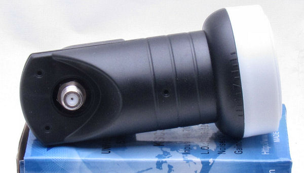
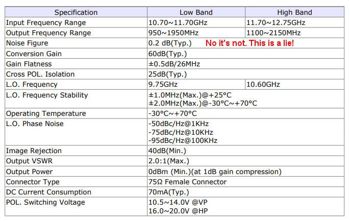
Totally ignore any noise figure claims. On the box this one says 0.2dB. That's either lying or wishful thinking. The basic device used in all of these LNBFs is the NE3503M04 (more recently replaced by the CE3514M4). The device itself has a noise figure of 0.45dB at 12GHz, with about 12dB gain. Practical circuits never reach the theoretical noise figure and you're not likely to get a state of the art noise figure in a circuit in a device selling for $5 and made by the tens of thousands in China. A more realistic Noise Figure, especially for 10.368 operation, is probably in the 1dB to 1.5dB range. That's not bad. A commercial preamp for 10Ghz costing $200 or more might have a NF around 0.7 to 0.8dB. With the LNBF there are no losses ahead of the preamp. No cables, no connectors, no relays. The waveguide probe goes directly from the LNA PCB trace into the waveguide. For what it's worth, the spec sheet for the Avenger KSC321S-2 is shown below. I wouldn't put much trust in the gain, NF and phase noise numbers.
Switching to "high band" is done my injecting a 22kHz audio tone at the IF output, but that's of no interest for 10Ghz EME.
Link -> Find LNBFs for sale on eBay
How do you use the LNBF for 10Ghz EME Rx?
The default output at 618MHz isn't a very convenient IF frequency. You can certainly use an RTL-DSL dongle to receive it, but probably not your main station rig will tune to 618 MHz. You could downconvert, and there some ideas on how to do that at https://amsat-uk.org/projects/uhf-vhf-receive-converter-for-satellite-lnb/. However, since you're probably going to want to improve the stability of the LNBF local oscillator anyway, you could also change it slightly to move the IF to a more convenient frequency. The particulate LNBF I will describe uses a 25MHz crystal. This is multiplied by 390x using a frequency synthesizer inside a "magic" chip on the LNBF board. This chip takes the 10Ghz signal and mixes it with the crystal multiplies by 390x. It then takes the resulting signal and puts it through an IF amplifier. Out of the box,the 25MHz crystal is multiplied by 390x to 9.750GHz. If you mix this with 10.368Ghz you get the difference product at 618Mhz.There is a problem though. The LNBF uses a free running, uncompensated, crystal oscillator. Stability with respect to temperature of such oscillators is not good. If the reference crystal changes frequency by just 1ppm the drift at 10GHz would be around 10KHz. The stability of the LNBF is listed in the specs as +/- 500KHz between -40C. and +60C. This is fine for a wideband TV signal, but not good at all for a weak narrow band 10Ghz EME signal. Even over a much smatter temperature range there will still be a pretty unacceptable amount of drift. You'll probably have trouble finding the EME signal and one you find it you'll have trouble keeping it in the passband of the receiver for very long, never mind attempting to decode it, especially with the LNBF outdoors and subject to outdoor temperature changes.
So what do you do?. The solution is to remove the 25Mhz crystal, install a small SMA connector on the LNBF and feed it a signal at around 25Mhz from stable source indoors. This could be a TCXO (temperature compensated crystal oscillator), or, better, an OCXD (Oven controlled crystal oscillator). This should provide much better frequency stability. At this point you can go one step further and feed it a stable signal at 25.476923 MHz (or somewhere close to that) to move the IF output frequency to 432MHz (very convenient if you have a 70cm radio). The internal chip will lock to this signal and generate a 9.935GHz local oscillator signal for the mixer. I've also injected a 25.400000 Mhz signal to generate a 9.906GHz local oscillation which converts the 10.368GHz signal down to 462MHz, still within the tuning range of my Yaesu FT-897. If you can generate a reference signal at 25.476923Mhz, the LO will be at 9936MHz and the IF will be at 432MHz.
It does not appear the chip will function well (if at all) at frequencies that yield a 144MHz or 1296MHz IF output. It might be possible to generate an IF output at 908MHz, but I didn't try since I have no 908MHz gear. The synthesizer is looking for a 25MHz reference, so the closer you are to that, the better chances it will lock onto the signal. In addition, the IF amplifier gain curve is designed for the 950 to 1950 MHz range. While it is pretty broadband it does drop significantly below 432, so even if you could get lock at 144MHz IF, conversion gain would suffer and performance along with it. The IF would be OK at 1296, but it doesn't seem to want to lock with the required 23.26153 MHz reference {which is what you would need for a 1296 IF). If you wanted to use a 144MHz receiver, the best course might be to take the 618MHz signal generated by using a stable 25MHz source and build a simple 618MHz to 144MHz converter.
Note that the IF output connector on the LNBF is a type "F" and is designed for 75 ohms. I run a 75 ohm TV cable from this connector into the shack. It's only operating in the UHF region and the LNBF has lots of IF gain, so the loss of the cable really isn't very important. If you really want to you could put some type of 75 ohm to 50 ohm transformer in the line before connecting it to a 50 ohm radio, but it's probably not necessary. What is necessary is a bias-T so that you can feed the LNFB with it's power (13.8v is fine) via the IF output cable.
Generating the required signal at or around 25MHz is left as "an exercise for the reader". There are lots of articles on how to build a basic frequency synthesizer base on chips like the Si5351A. Take a look at The QRP Labs Website for some ideas (and kits). Ideally the synthesizer would use an OCXO (Oven Controlled Crystal Oscillator) or be GPS locked for stability. There are also some 0-55MHz Module AD9850 DDS synthesizers with digital display and 1Hz setting resolution available from China via ebay. They may work, but documentation looks a bit sketchy. You can also buy a good 10MHz OCXO from ebay for under $20 and use an inexpensive frequency multiplier chip (e.g. the NB3N511) to multiply the output by 2.5x to give an OCXO derived 25MHz signal. You can also buy a programmable GPS referenced clock oscillator from Leo Bodener Electronics
NEXT: Modifying the LNBF